Weslo Daybreak 408 Spa English Manual - Page 11
Spa Shell Diagram
 |
View all Weslo Daybreak 408 Spa manuals
Add to My Manuals
Save this manual to your list of manuals |
Page 11 highlights
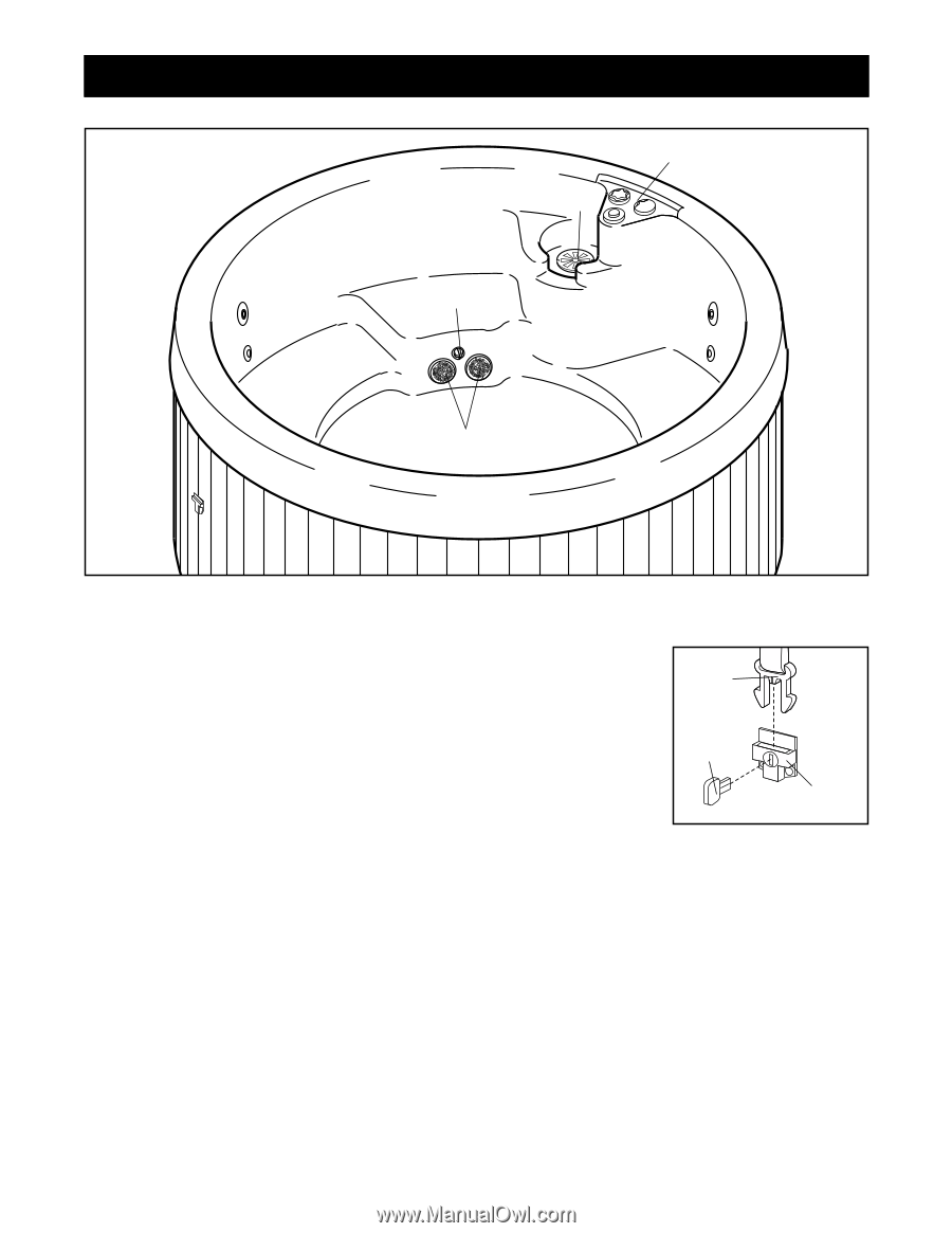
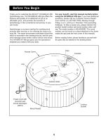
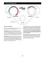
Spa Shell Diagram C D B A SPA OPERATION Refer to the diagram above. The function of each component is explained below. The suction vents (A) located near the floor of the spa bring water into the pump in order to operate the system. The suction covers should always be in place over the suction vents. Never operate the spa without the suction covers in place. The filter (B) can be removed for cleaning and replacement (see CHECKING AND CLEANING THE FILTER on page 13). The temperature probe (C) reads the current water temperature. Use of the console (D) is explained on page 12 of this manual. The hydrotherapy spa offers automatic freeze protection. If the water temperature falls below 40˚F, the pump will begin circulating the water in order to prevent the water from freezing. SECURING THE SPA COVER To secure the spa cover, snap the latches on the spa cover into the buckles on the side panels. Latch Key To lock the buckles, insert the key and turn it clockwise one quar- Buckle ter turn. To unlock the buckles, insert the key and turn it counterclockwise one quarter turn. Always keep the buckles locked when the spa is not in use. Keep the keys in a safe place, out of the reach of children. 11
-
 1
1 -
2
-
3
-
4
-
5
-
 6
6 -
 7
7 -
 8
8 -
 9
9 -
 10
10 -
 11
11 -
 12
12 -
 13
13 -
 14
14 -
 15
15 -
 16
16 -
17
-
18
-
19
-
20
 |
 |