Weslo Expert 350 English Manual - Page 4
Assembly
 |
View all Weslo Expert 350 manuals
Add to My Manuals
Save this manual to your list of manuals |
Page 4 highlights
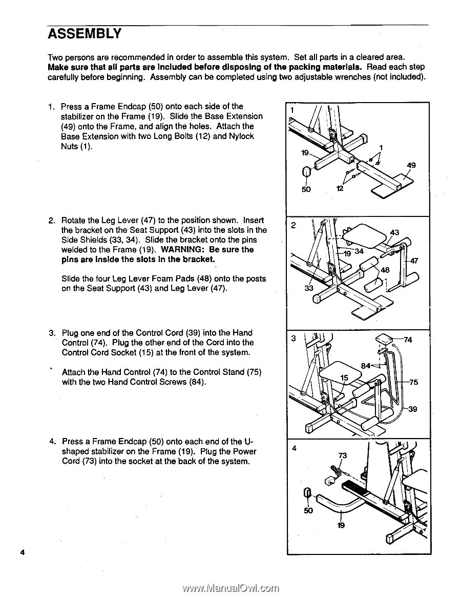
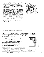
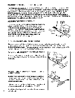
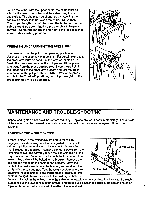
ASSEMBLY Two persons are recommended in order to assemble this system. Set all parts in a cleared area. Make sure that ail parts are included before disposing of the packing materials. Read each step carefully before beginning. Assembly can be completed using two adjustable wrenches (not included). 1. Press a Frame Endcap (50) onto each side of the stabilizer on the Frame (19). Slide the Base Extension (49) onto the Frame, and align the holes. Attach the Base Extension with two Long Bolts (12) and Nylock Nuts (1). 1 it i 19 49 50 12 2. Rotate the Leg Lever (47) to the position shown. Insert the bracket on the Seat Support (43) into the slots in the 2 Side Shields (33, 34). Slide the bracket onto the pins welded to the Frame (19). WARNING: Be sure the pins are inside the slots in the bracket. 19 34 47 Slide the four Leg Lever Foam Pads (48) onto the posts on the Seat Support (43) and Leg Lever (47). 3. Plug one end of the Control Cord (39) into the Hand Control (74). Plug the other end of the Cord into the Control Cord Socket (15) at the front of the system. Attach the Hand Control (74) to the Control Stand (75) with the two Hand Control Screws (84). 3 \ \ c? b; 74 84 ---, 75 39 4. Press a Frame Endcap (50) onto each end of the U- shaped stabilizer on the Frame (19). Plug the Power 4 Cord (73) into the socket at the back of the system. 73 . , 50 - _ 19 4
-
 1
1 -
 2
2 -
 3
3 -
 4
4 -
 5
5 -
 6
6 -
 7
7 -
 8
8 -
 9
9 -
 10
10 -
11
-
12
 |
 |