Weslo Momentum 850 Instruction Manual - Page 5
Assembly, Maintenance And Troubleshooting
 |
View all Weslo Momentum 850 manuals
Add to My Manuals
Save this manual to your list of manuals |
Page 5 highlights
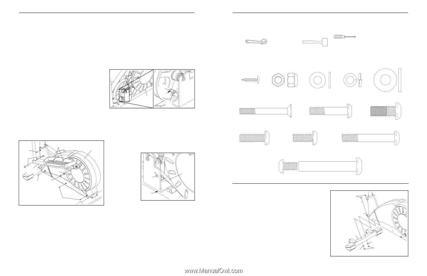
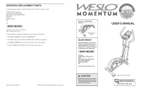
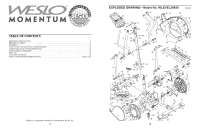
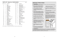
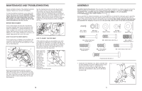
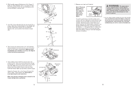
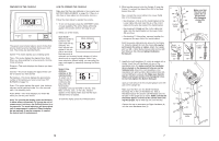
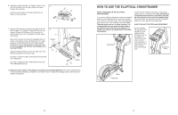
MAINTENANCE AND TROUBLESHOOTING Inspect and tighten all parts of the elliptical crosstrainer regularly. Replace any worn parts immediately. To clean the elliptical crosstrainer, use a damp cloth and a small amount of mild soap. Important: Keep liquids away from the console, place only a sealed water bottle in the water bottle holder, and keep the console out of direct sunlight. During storage, remove the batteries from the console. See the drawing below and locate the Reed Switch (53). Loosen, but do not remove, the indicated M4 x 16mm Screw (42). Slide the Reed Switch slightly toward or away from the Magnet (58) on the flywheel. Retighten the Screw. Turn the left Pedal Disc (15) for a moment. Repeat until the console displays correct feedback. When the Reed Switch is correctly adjusted, reattach the Left Side Shield (3) and the Left Pedal Arm (11). BATTERY REPLACEMENT If the console display becomes dim, the batteries should be replaced; most console problems are the result of low batteries. To replace the batteries, see step 5 on page 6 and remove the console from the upright. Next, see step 4 on page 6 and insert three batteries into the console. Reattach the console to the upright, being careful not to pinch the wires. 58 53 15 42 HOW TO ADJUST THE REED SWITCH If the console does not display correct feedback, the reed switch should be adjusted. To adjust the reed switch, you must remove the Left Pedal Arm (11) and the Left Side Shield (3). 56 42 3 40 11 35 42 22 42 Remove the Pedal Arm Bolt Set (40), the M10 x 25mm Patch Screw (22), and the M10 Washer (35) from the Left Pedal Arm (11). Remove the Left Pedal Arm. Next, remove the two M4 x 25mm Screws (56) and the four M4 x 16mm Screws (42) from the Left Side Shield (3). HOW TO ADJUST THE DRIVE BELT If the pedals slip whilst you are pedaling, even when the resistance is adjusted to the highest setting, the Drive Belt (19) may need to be adjusted. To adjust the Drive Belt, you must first remove the left side shield. See HOW TO ADJUST THE REED SWITCH at the left and remove the left side shield. Next, loosen the M8 x 22mm Flat Head Screw (41) and turn the M10 x 60mm Button Bolt (62) until 41 19 the Drive Belt (19) is tight. When the Drive Belt is tight, 62 tighten the Flat Head Screw. Reattach the left side shield. 12 ASSEMBLY Assembly requires two persons. Place all parts of the elliptical crosstrainer in a cleared area and remove the packing materials. Do not dispose of the packing materials until assembly is completed. In addition to the included hex keys, assembly requires a phillips screwdriver , an adjustable wrench , and a rubber mallet . As you assemble the elliptical crosstrainer, use the drawings below to identify the small parts used in assembly. The number in parenthesis below each drawing refers to the key number of the part, from the PART LIST on page 14. The second number refers to the quantity used in assembly. Note: Some small parts may have been pre-assembled for shipping. If a part is not in the parts bag, check to see if it has been pre-assembled. M4 x 16mm Screw (42)-5 M8 Nylon Locknut (38)-8 M8 Washer (48)-4 M8 Split Washer (59)-6 M10 Washer (35)-2 M6 x 48mm Flat Head Screw (36)-4 M8 x 38mm Button Bolt (50)-4 M10 x 25mm Patch Screw (22)-2 M8 x 25mm Button Screw (45)-1 M8 x 19mm Button Screw (68)-6 M8 x 53mm Button Bolt (34)-4 Pedal Arm Bolt Set (40)-2 1. Identify the Front Stabilizer (10), which is narrower than the Rear Stabilizer (not shown). Whilst another person 1 lifts the front of the Frame (1), attach the Front Stabilizer to the Frame with two M8 x 53mm Button Bolts (34), two M8 Washers (48), and two M8 Nylon Locknuts (38). 34 1 10 48 38 48 5
-
 1
1 -
 2
2 -
 3
3 -
 4
4 -
 5
5 -
 6
6 -
 7
7 -
 8
8
 |
 |