Weslo Momentum 850 Instruction Manual - Page 7
How To Operate The Console
 |
View all Weslo Momentum 850 manuals
Add to My Manuals
Save this manual to your list of manuals |
Page 7 highlights
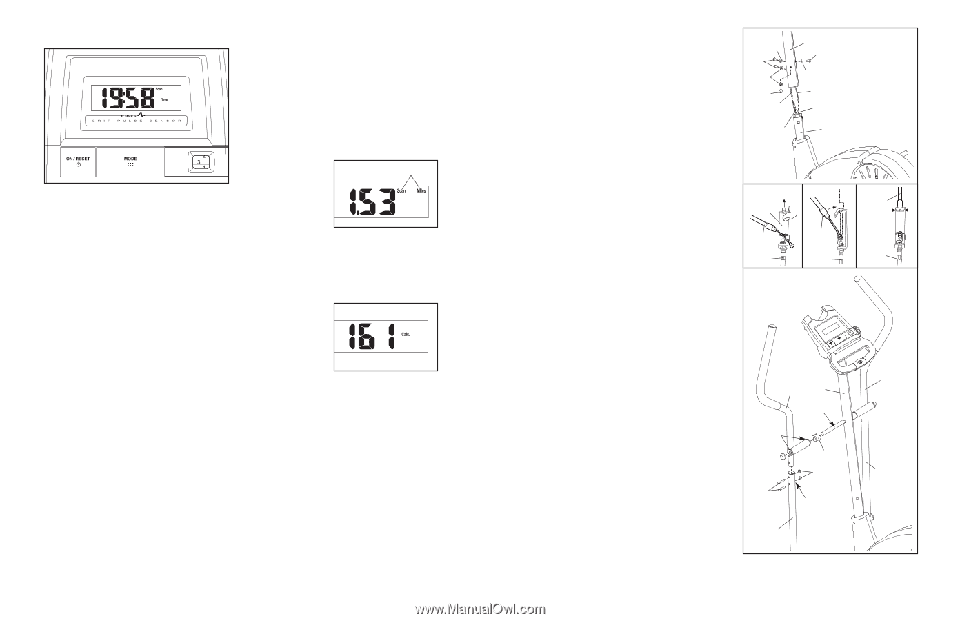
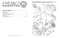
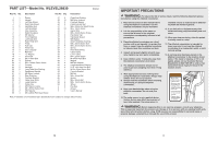
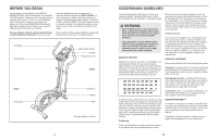
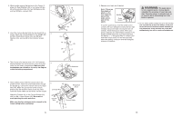
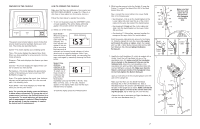
FEATURES OF THE CONSOLE The easy-to-use console features seven modes that provide instant exercise feedback during your workouts. The modes are described below. Speed-This mode displays your pedalling speed. Time-This mode displays the elapsed time. Note: When you stop pedalling for a few seconds, the time mode will pause. Distance-This mode displays the distance you have pedalled. Calories-This mode displays the approximate number of calories you have burned. Fat Calories-This mode displays the approximate number of fat calories you have burned (see FAT BURNING on page 13). Scan-This mode displays the speed, time, distance, calories, and fat calories modes, for a few seconds each, in a repeating cycle. Pulse (BPM)-This mode displays your heart rate when you use the pulse sensor. Note: The console can display speed and distance in either miles or kilometers. To change the unit of measurement, hold down the On/Reset button for a few seconds. The mode indicators will show which unit of measurement is selected. When the batteries are replaced, it may be necessary to reselect the desired unit of measurement. HOW TO OPERATE THE CONSOLE Make sure that there are batteries in the console (see BATTERY REPLACEMENT on page 12). If there is a thin sheet of clear plastic on the console, remove it. Follow the steps below to operate the console. 1. To turn on the power, press the ON/RESET button or begin pedalling. The entire display will briefly appear; the console will then be ready for use. 2. Select one of the modes: Scan mode- When the power is Mode Indicators turned on, the scan mode will be selected. The scan indicator will appear in the dis- play to show that the scan mode is selected, and a second mode indicator will show which mode is currently displayed. Note: If you have selected a different mode, you can select the scan mode again by repeatedly pressing the Mode button. Speed, time, distance, calories, or fat calories mode- To select one of these modes for continuous display, press the Mode button repeatedly until only the MPH (or Km/H), Time, Miles (or Kms), Cals., or Fat Cals. indicator appears in the display. Make sure that the Scan indicator does not appear. To reset the display, press the On/Reset button. 10 6. Whilst another person holds the Upright (2) near the Frame (1), connect the Upper Wire (44) to the Reed Switch Wire (53). Next, connect the control cable to the Lower Cable (55) in the following way: • See drawing A. Pull up on the metal bracket on the Lower Cable (55), and insert the tip of the control cable into the wire clip inside of the metal bracket. • See drawing B. Firmly pull the control cable and slide it into the metal bracket on the Lower Cable (55) as shown. • See drawing C. Using pliers, squeeze together the prongs on the upper end of the metal bracket. Push the excess cable and wire down into the Frame (1). Slide the Upright (2) onto the Frame. Be careful not to pinch the wires or cables. Attach the Upright with four M8 x 19mm Button Screws (68) and four M8 Split Washers (59). Do not tighten the Button Screws yet. 7. Identify the Left Handlebar (6), which is marked with a sticker. Insert the Left Handlebar into one of the Handlebar Arms (5); make sure that the Handlebar Arm is turned so the hexagonal holes are on the indicated side. Attach the Left Handlebar to the Handlebar Arm with two M8 x 38mm Button Bolts (50) and two M8 Nylon Locknuts (38). Make sure that the Nylon Locknuts are inside of the hexagonal holes. Do not fully tighten the Button Bolts yet. Apply a small amount of the included grease to the left axle on the Upright (2). Make sure that there are two Small Handlebar Bushings (49) in the Left Handlebar (6). Slide a Handlebar Spacer (47) and the Left Handlebar onto the left axle on the Upright (2) as shown. Make sure that the Handlebar Spacer is turned so the curved side is facing the Upright. Tap an Axle Cap (14) onto the axle. Repeat this step to assemble the Right Handlebar (8) and the other Handlebar Arm (5). 6 59 68 59 68 Control Cable 55 2 68 59 44 53 1 Make sure that the wires and cables do not get pinched and damaged during this step. A Metal Bracket Control Cable 55 7 B Control Cable 55 C Control Cable 55 8 6 2 Grease 49 14 47 38 5 50 Hexagonal Holes 5 7
-
 1
1 -
 2
2 -
 3
3 -
 4
4 -
 5
5 -
 6
6 -
 7
7 -
 8
8
 |
 |