Western Digital HPBAAD0020HBK Quick Install Guide (pdf) - Page 3
Set the Jumpers, Install the Hard Drive
 |
UPC - 718037752358
View all Western Digital HPBAAD0020HBK manuals
Add to My Manuals
Save this manual to your list of manuals |
Page 3 highlights
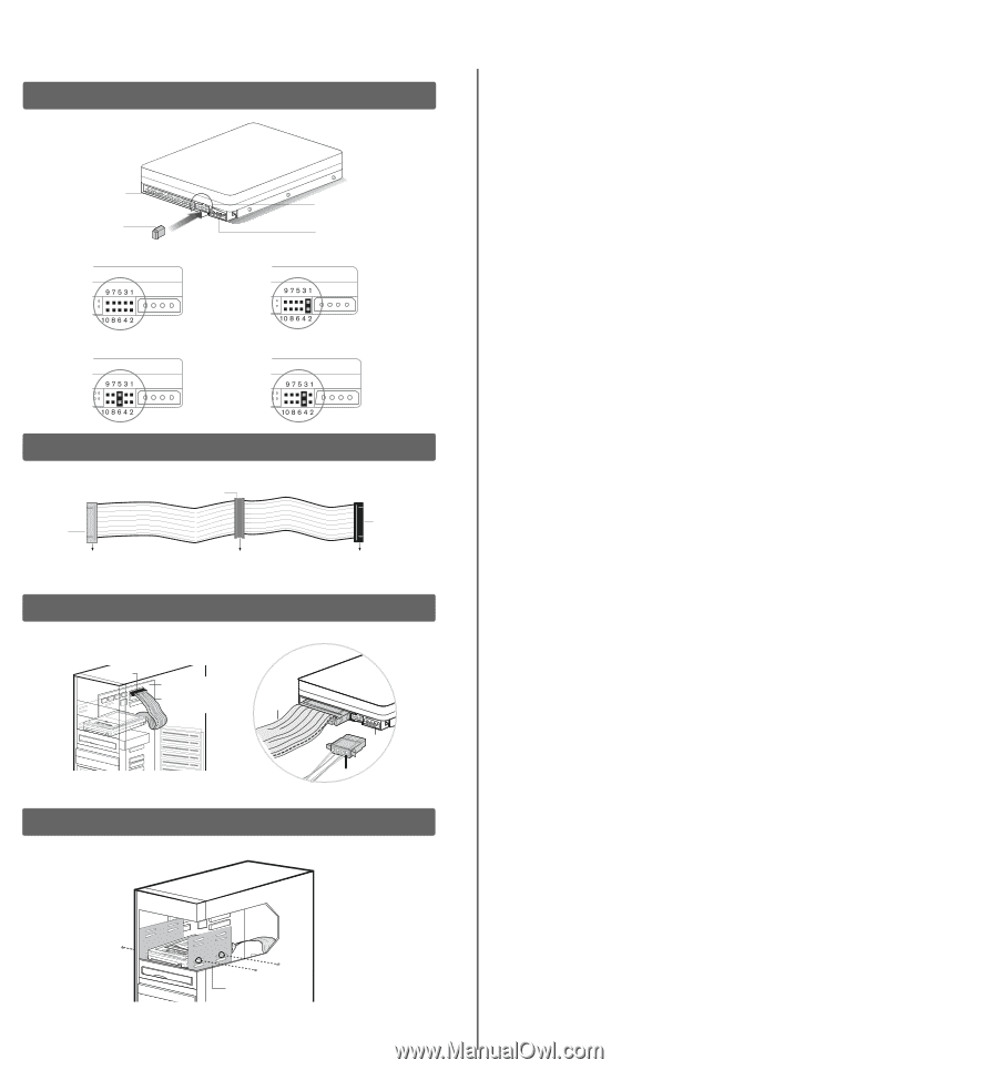
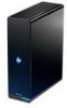
Figure 1 40-pin IDE connector Jumper shunt Single Dual (Master) Jumper block Power supply connector Cable Select (Default Setting) Dual (Slave) Figure 2 Gray 40-pin connector Blue 40-pin connector SYSTEM Figure 3 SECONDARY DRIVE (SLAVE) Black 40-pin connector PRIMARY DRIVE (MASTER) Pin 1 Motherboard Interface cable from hard drive IDE interface cable Power connector Power supply cable Figure 4 Mounting frame 2. Set the Jumpers WD EIDE hard drives have a 10-pin jumper block located next to the 40-pin IDE connector on the hard drive. Jumper the drive according to your desired configuration (i.e., Cable Select, Master/Slave, or Single). Refer to the illustration on the left (Figure 1) for reference. A. Cable Select Cable Select is the default setting for WD EIDE hard drives and requires a standard 40-pin, 80-conductor cable (not included). If your system supports Cable Select, there is no need to reposition the jumper shunt on the drive. If you are installing your new WD hard drive with an existing IDE drive on the cable, make sure that the other drive is also jumpered as Cable Select. If your system does not support Cable Select or if you are uncertain, use the Single or Master/Slave configuration. Note: Cable Select mode is not supported by Macintosh's built-in IDE/ATA controller. You must use the Master/Slave jumper setting. B. Standard Jumper Settings (Master/Slave or Single Configuration) 1. If installing your new WD hard drive as the only device on the cable, use the Single setting (no jumper shunt required). 2. If installing your new WD hard drive as the Master device on the cable with two IDE drives, use the Master setting. 3. If installing your new WD hard drive as a secondary device on the cable, use the Slave setting. 3. Install the Hard Drive Important: Your new WD hard drive must be installed using a standard 40-pin, 80-conductor IDE interface cable. Note: Installation instructions will vary depending on your drive configuration. Carefully follow the appropriate procedure that corresponds to your drive configuration. 1. If installing the hard drive as the only device on the cable, connect the black connector of the IDE interface cable to the drive and the blue end of the cable to the IDE connector on the motherboard. Proceed to step 3. 2. If installing two drives on the same IDE cable, a. Jumper the bootable drive as Master and the other drive as Slave; then connect the Master drive to the black connector of the IDE interface cable and the Slave drive to the gray connector. b. Connect the blue end of the IDE interface cable to the IDE connector on the motherboard (Figure 2). 3. Attach the power supply cable to the 4-pin power connector on the drive (Figure 3). 4. Slide the hard drive into an available 3.5-inch drive bay and secure the drive with the four mounting screws provided (two on each side). For proper grounding, use screws in the hole positions as shown (Figure 4). 5. Verify all cable connections. Replace and secure the system cover. Reconnect the power cord and power on the computer. -2-
-
 1
1 -
 2
2 -
 3
3 -
 4
4 -
 5
5 -
 6
6 -
 7
7
 |
 |