Whirlpool SC8720EDB Installation Instructions - Page 6
Installation steps - 30 inch gas cooktop
 |
UPC - 050946528700
View all Whirlpool SC8720EDB manuals
Add to My Manuals
Save this manual to your list of manuals |
Page 6 highlights
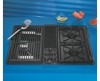
Installation steps Note: Cooktop shown with optional grill accessory. A Preparation WARNING Excessive Weight Hazard Use two or more people to move and install cooktop. Failure to do so can result in back or other injury. B Align cooktop in cutout A Blower range setting B Installation 3. Insert downdraft cooktop into cutout. Check that: ࠜ cooktop is centered in cutout. ࠜ front edge of downdraft cooktop is at least 1-1/2" (3.8 cm) from front edge of countertop and parallel to countertop. ࠜ side edge of cooktop is at least 2 inches (5.1 cm) from side wall. E Check each burner for proper flame D Gas supply connection C Vent system connection C Vent connection 4. Connect vent system. See "Venting requirements," pages 3-4. Use duct tape to seal all joints. Vent must end with a wall or roof cap outside the building. 1. Remove the downdraft cooktop from packaging. 2. Check equivalent vent length to determine if blower should be set at "Low" or "High" range (see chart on page 4 to determine equivalent vent system length). If vent system length is greater than 30 feet (9.1m), shift the blower range setting from "Low" to "High" (see instructions on page 4 for shifting the blower range). If blower must be shifted to "High" range, do it now. D Gas connection IMPORTANT: All connections must be wrench-tightened. Do Not make connections to the gas regulator too tight. Making the connection too tight may crack the regulator and cause a gas leak. Do Not allow the regulator to turn on the pipe when tightening fittings. All connections must be wrench-tightened. burner box 5. Assemble the flexible connector 1/2" from the gas supply pipe nipple to the pressure regulator in order: manual shutoff valve, 1/2" nipple, flexible 1/2" adapter, flexible connector connector, 1/2" adapter, 1/2" nipple and pressure regulator. Or install rigid piping as required. 1/2" nipple pressure regulator 1/2" adapters manual shutoff valve 6. Use pipe-joint compound made for use with L.P. gas to seal all pipe thread gas connections. If flexible connectors are used, be certain connectors are not kinked. shutoff valve "open" position to downdraft cooktop to gas supply 7. Open the manual shutoff valve in the gas supply line. Wait a few minutes for the gas to move through the line. 8. Use a brush and liquid detergent to test all gas connections. Bubbles around the connections will indicate a leak. If a leak appears, shut off gas valve controls and adjust connections. Then check connections again. NEVER TEST FOR GAS LEAKS WITH A MATCH OR OTHER FLAME. Clean all detergent from the cooktop. Page 5
-
 1
1 -
 2
2 -
 3
3 -
 4
4 -
 5
5 -
 6
6 -
 7
7 -
 8
8 -
 9
9
 |
 |
