Whirlpool SC8720EDB Installation Instructions - Page 7
Check operation - pan
 |
UPC - 050946528700
View all Whirlpool SC8720EDB manuals
Add to My Manuals
Save this manual to your list of manuals |
Page 7 highlights
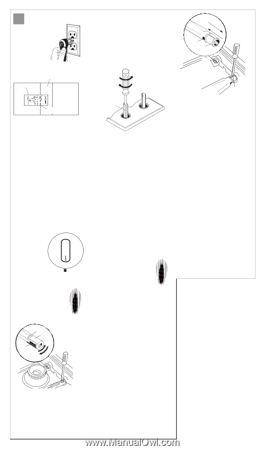
E Check operation 9. Plug the power supply cord into the grounded outlet. flow tester air intake flow tester 12. Push in and turn each surface burner control knob to "LITE" position and then to "LO" position. The low flame should be a minimum, steady blue flame. Do Not use a metal blade to pry off control knob; this could damage the product. If the control knob cannot be easily removed, tuck a cloth under the knob and pull upward on cloth with steady, even pressure to remove knob. counterclockwise to increase flame clockwise to reduce flame edge of line on flow tester front of cooktop 10. Check for proper venting: • Check that the air filter is in place. • Align the dotted line labeled for "cooktop models" on the flow tester with the edge of the intake on the left side of the cooktop near the center. • Turn on the downdraft system: If the card is pulled into the air intake, your downdraft is working properly. If the card is not pulled into the system, see "Venting requirements," Pages 3-4, and check vent installation for possible causes. Electronic ignitions system Cooktop burners use electronic ignitors in place of standing pilots. When the cooktop control knob is turned to the "LITE" position, the system creates a spark to light the burner. This sparking continues until the control knob is turned to the desired setting. Check operation of right-side surface burners module OFF MED LO 11. Push down and turn each surface burner control knob to "LITE" position. The flame should light within LITE HI 4 seconds. Turn the control knob to "HI" position after burner lights. Do Not leave the knob in the "LITE" position after burner lights. Check each surface burner for proper flame at "HI" setting. The small inner cone should have a very distinct, blue flame that is 1/4" (0.6 cm) to 1/2" long (1.3 cm). The outer cone is not as distinct as the inner cone. Turn surface burner control knobs to "OFF" position. screw air shutter air opening to open to close To adjust surface burner air shutter valve stem If the low flame needs adjusting - • Remove the control knob and turn the adjustment screw in the center of the valve stem. Do Not turn screw more than 1/2 revolution in either direction. • Replace the control knob. Check the adjustment by turning the control knob from "HI" to "LO" several times. The burner is properly adjusted when the low flame remains steady and the burner does not go out. • Turn control knob to "OFF" position. • Repeat if necessary for other surface burner. Check operation of left-side surface burners or optional grill module 13. Use module instructions to install left-side surface burner or optional grill module. Surface burners module: Push in and turn right surface burner control knob to "LITE" position. The flame should light within 4 seconds. Turn the control knob to "HI" position after burner lights. Do Not leave the knob in the "LITE" position after burner lights. Check surface burner for proper flame. The small inner cone will be similar to the right-side module surface burner flames, but will be shorter and softer. The outer cone is not as distinct as the inner cone. Turn surface burner control knob to "OFF" position. Repeat for left surface burner control knob. Grill module: Remove grill grates and burner pan. Push in and turn right control knob to "LITE" position. The flame should light within 4 seconds. Turn the control knob to "HI" position after burner lights. Do Not leave the knob in the "LITE" position after burner lights. Check the grill burner for proper flame. The small inner cone will be similar to the rightside surface burner flames, but will be shorter and softer. The outer cone is not as distinct as the inner cone. Turn grill burner control knob to "OFF" position. Repeat for left grill burner control knob. to open air opening to close air shutter To adjust grill burner air shutter grill burner air shutter If burner flames need adjusting - • Remove surface burner grates and burner pan. • Push in and turn control knob to "LITE" position and then to "HI" position. • The right air shutter controls the front half of the burner; the left air shutter controls the rear half. Insert a screwdriver blade in the air shutter slot that needs adjusting and lightly twist the screwdriver to slide air shutter backward or forward to adjust the flame. Adjust the burner air shutter to the widest opening that will not cause the flame to lift or blow off the burner. • Turn control knob to "OFF" position. • Repeat if necessary for other burner control knob. 14. Push in and turn each control knob to "LITE" position and then to "LO" position. The low flame should be a minimum, steady blue flame. If low flame needs adjusting - • Remove the control knob and turn the adjustment screw in the center of the valve stem. Do Not turn screw more than 1/2 revolution in either direction. • Replace the control knob. Check the adjustment by turning the control knob from "HI" to "LO" several times. The burner is properly adjusted when the low flame remains steady and the burner does not go out. • Turn control knob to "OFF" position. • Repeat if necessary for other burner control knob. • Replace surface burner grates and burner pan or grill grates and burner pan. You have just finished installing your new downdraft cooktop. To get the most efficient use from your new cooktop, read your Use & Care Guide. Keep Installation Instructions and Guide close to cooktop for easy reference. surface burner air shutter If surface burner flames need adjusting - • Remove burner grate and burner pan. • Turn control knob to "HI" position. • Loosen the air shutter screw. Adjust the air shutter to the widest opening that will not cause the flame to lift or blow off the burner. • After adjusting air shutter, tighten air shutter screw. • Turn control knob to "OFF" position. • Replace burner grate and burner pan. • Repeat if necessary for other surface burner. Page 6
-
 1
1 -
 2
2 -
 3
3 -
 4
4 -
 5
5 -
 6
6 -
 7
7 -
 8
8 -
 9
9
 |
 |