Whirlpool W5CG3024XS Installation Instructions - Page 10
Complete Connection - parts
 |
UPC - 883049225630
View all Whirlpool W5CG3024XS manuals
Add to My Manuals
Save this manual to your list of manuals |
Page 10 highlights
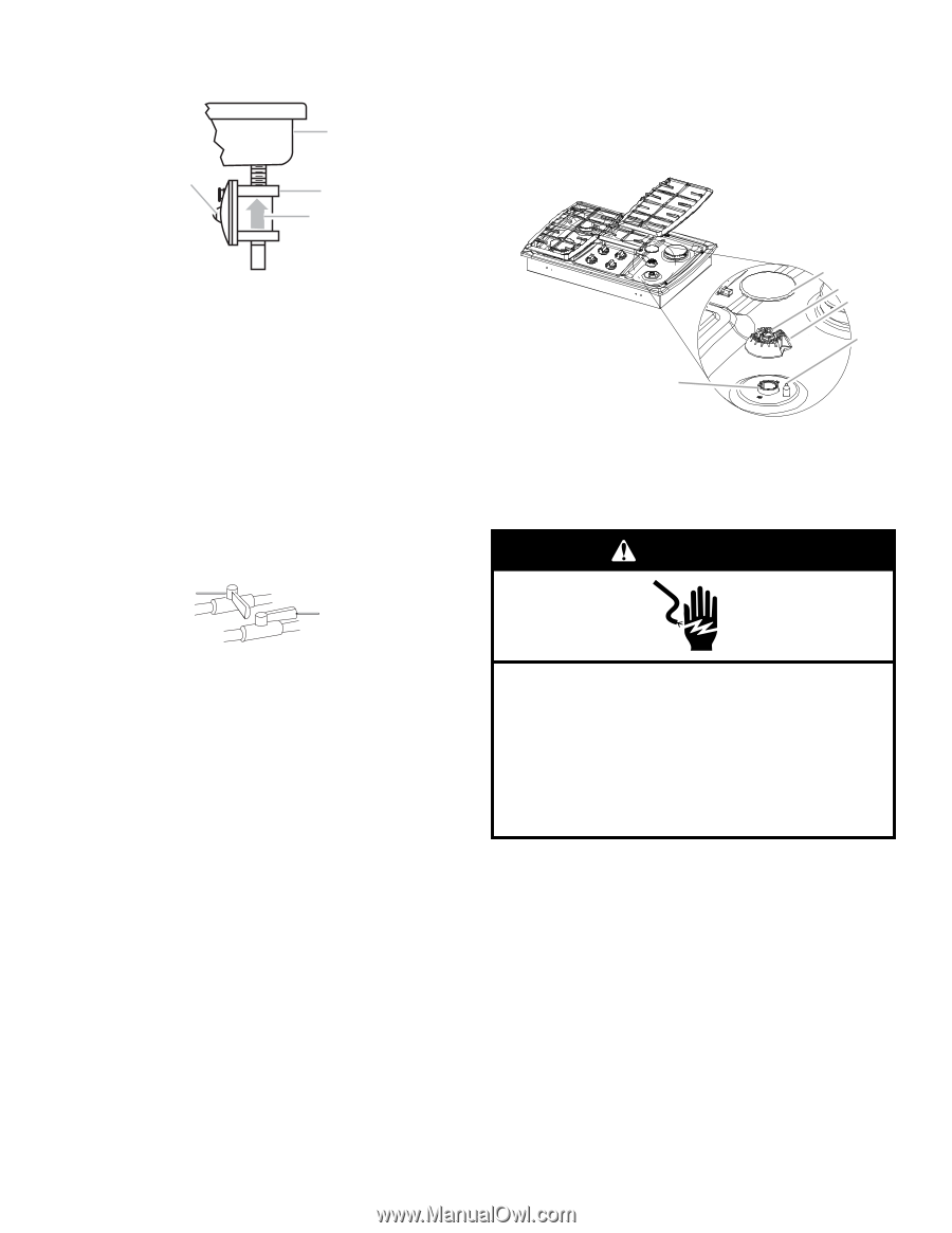
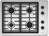
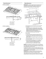
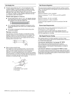
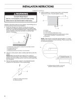
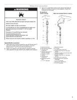
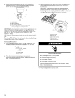
4. Install the pressure regulator with the arrow pointing up toward the bottom of the cooktop base and in a position where you can reach the regulator access cap. B A C D 3. Remove surface burner caps, burner base and grates from parts package. Align notches in burner caps with pins in burner base. Align orifice holder in burner base with igniter electrode. Burner caps should be level when properly positioned. If burner caps are not properly positioned, surface burners will not light. Place burner grates over burners and caps. A. Access cap B. Rear of cooktop C. Gas pressure regulator D. Up arrow. Regulator must be installed with arrow pointing up to cooktop bottom. IMPORTANT: All connections must be wrench-tightened. Do not make connections to the gas regulator too tight. Making the connections too tight may crack the regulator and cause a gas leak. Do not allow the regulator to turn on the pipe when tightening fittings. Use only pipe-joint compound made for use with Natural and LP gas. Do not use TEFLON® tape. You will need to determine the fittings required depending on your installation. Complete Connection 1. Open the manual shutoff valve in the gas supply line. The valve is open when the handle is parallel to the gas pipe. A B B C D E A A. Orifice holder B. Burner cap C. Gas tube opening D. Burner base E. Igniter electrode WARNING A. Closed valve B. Open valve 2. Test all connections by brushing on an approved noncorrosive leak-detection solution. Bubbles will show a leak. Correct any leak found. Electrical Shock Hazard Plug into a grounded 3 prong outlet. Do not remove ground prong. Do not use an adapter. Do not use an extension cord. Failure to follow these instructions can result in death, fire, or electrical shock. 4. Plug into a grounded 3 prong outlet. 10
-
 1
1 -
2
-
3
-
4
-
 5
5 -
 6
6 -
 7
7 -
 8
8 -
 9
9 -
 10
10 -
 11
11 -
 12
12 -
 13
13 -
 14
14 -
 15
15 -
16
-
17
-
18
-
19
-
20
-
21
-
22
-
23
-
24
 |
 |