Whirlpool WGD5800S Installation Instructions - Page 5
Warning - appliances
 |
View all Whirlpool WGD5800S manuals
Add to My Manuals
Save this manual to your list of manuals |
Page 5 highlights
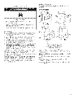
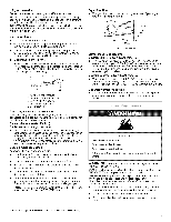
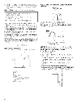
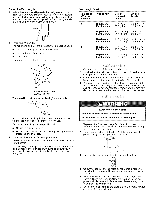
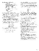
L.R gas conversion: Conversion must be made by a qualified technician. No attempt shall be made to convert the appliance from the gas specified on the model/serial rating plate for use with a different gas without consulting the serving gas supplier. IMPORTANT: The gas installation must conform with local codes, or in the absence of local codes, with the National Fuel Gas Code, ANSI Z223.1/NFPA 54. Gas Supply Line: • r/2" IPS pipe is recommended. • %" approved tubing is acceptable for lengths under 20 ft (6.1 m) if local codes and gas supplier permit. • Must include 1/8"NPT minimum plugged tapping accessible for test gauge connection, immediately upstream of the gas connection to the dryer (see illustration). • Must include a shutoff valve: An individual manual shutoff valve must be installed within six (6) feet (1.8 m) of the dryer in accordance with the National Fuel Gas Code, ANSI Z223.1. The location should be easy to reach for opening and closing. A C E B D A. _" flexible gas connector B. _" pipe to flare adapter fitting C. _" NPT plugged tapping D. Y/' NPT gas supply line E, Gas shutoff valve Gas supply connection requirements There are many methods by which your gas dryer can be connected to the gas supply. Listed here are some guidelines for two different methods of connection. Option 1 (Recommended Method) Flexible stainless steel gas connector: • If local codes permit, use a new flexible stainless steel gas connector (Design Certified by the American Gas Association or CSA International) to connect your dryer to the rigid gas supply line. Use an elbow and a %" flare x %" NPT adapter fitting between the stainless steel gas connector and the dryer gas pipe, as needed to prevent kinking. Option 2 (Alternate Method) Approved aluminum or copper tubing: • Lengths under 20 ft (6.1 m) can use %" approved tubing (if codes and gas supplier permit). • If you are using natural gas, do not use copper tubing. • %" flare x %" NPT adapter fitting between dryer pipe and %" approved tubing. • Lengths over 20 ft (6.1 m) should use larger tubing and a different size adapter fitting. • If your dryer has been converted to use L.R gas, %" L.R compatible copper tubing can be used. If the total length of the supply line is more than 20 ft (6.1 m), use larger pipe. NOTE: Pipe joint compounds that resist the action of L.R gas must be used. Do not use TEFLOW _ tape. Dryer Gas Pipe • The gas pipe that comes out through the rear of your dryer has a %" male pipe thread. (3"2im) A--_ 9,/4" 2:/1 (23.5cm} A. _" NPT dryer pipe Burner Input Requirements: Elevations up to 10,000 ft (3,048 meters): • The design of this dryer is certified by CSA International for use at altitudes up to 10,000 ft (3,048 m) above sea level at the B.T.U. rating indicated on the model/serial number plate. Burner input adjustments are not required when the dryer is operated up to this elevation. Elevations above 10,000 ft (3,048 meters): • When installed above 10,000 ft (3,048 m) a 4% reduction of the burner B.T.U. rating shown on the model/serial number plate is required for each 1,000 ft (305 m) increase in elevation. Gas Supply Pressure Testing • The dryer must be disconnected from the gas supply piping system during pressure testing at pressures greater than 1/2psi. Fire Hazard Use a heavy metal vent. Do not use a plastic vent. Do not use a metal foiB vent. FaUure to follow these instructions or fire. can recur in death WARNING: To reduce the risk of fire, this dryer MUST BE EXHAUSTED OUTDOORS. 4" (10.2 cm) heavy metal exhaust vent and clamps must be used. DURASAFE TM venting products are recommended. DURASAFE TM vent products can be purchased from your dealer or by calling Whirlpool Parts and Accessories. For more information, see the "Assistance or Service" section of your "Dryer User Instructions." • The dryer exhaust must not be connected into any gas vent, chimney, wall, ceiling, or a concealed space of a building. • Do not use an exhaust hood with a magnetic latch. • Do not install flexible metal vent in enclosed walls, ceilings or floors. 1-®TEFLON is a registered trademark of E.I. Du Pont De Nemours and Company.
-
 1
1 -
 2
2 -
 3
3 -
 4
4 -
 5
5 -
 6
6 -
 7
7 -
 8
8 -
 9
9 -
 10
10 -
 11
11 -
12
-
13
-
14
-
15
-
16
-
17
-
18
-
19
-
20
 |
 |