Whirlpool WML55011HS Installation Instructions - Page 7
Prepare Upper Cabinet - dimensions
 |
View all Whirlpool WML55011HS manuals
Add to My Manuals
Save this manual to your list of manuals |
Page 7 highlights
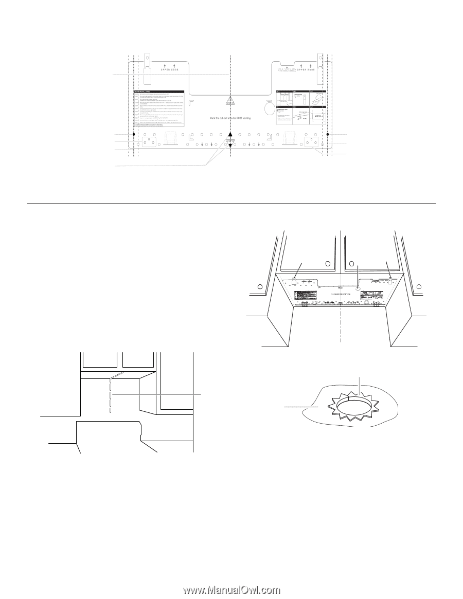
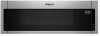
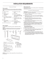
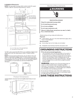
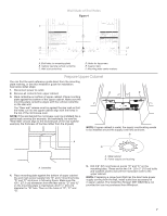
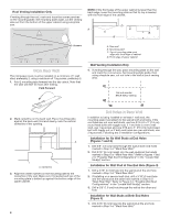
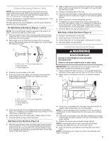
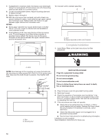
Wall Studs at End Holes Figure 4 B A,D E C REAR WALL REAR WALL A,D C E F A. End holes (on mounting plate) B. Cabinet opening vertical centerline C. Wall stud centerlines D. Holes for lag screws E. Support tabs F. Mounting plate center markers Prepare Upper Cabinet You can find the quick reference guide direct from the mounting plate marking, or use this installation guide for installation. See below install steps: 1. Disconnect power to outlet. 2. Remove all contents from upper cabinet. 3. Mark centerline on bottom of upper cabinet. Place mounting plate against the bottom of the upper cabinet. Make sure the mounting plate centerline aligns with the vertical centerline on the rear wall. The "Rear wall" arrows must be against the rear wall so that the holes cut into the upper cabinet align with the holes in the top of the microwave oven. NOTE: If the wall behind the microwave oven (as installed) has a partial wall covering (for example, tile backslash), be sure the "Rear Wall" arrows align to the thickest part of the rear wall (for example, the thickness of the tiles rather than the drywall). D G E t NOTE: If upper cabinet is metal, the supply cord bushing needs to be installed around the supply cord hole as shown. B A A A. Centerline 4. Place mounting plate against the bottom of upper cabinet line and mark power supply hole "G" and 2 mounting holes "D" and "E" as shown in following figure. Make sure the 103⁄4" (27.3 cm) dimension from the rear wall to "D" and "E" on the mounting plate is maintained. And 11⁄2" (3.8 cm) diameter for "G" hole. Then cut the holes of "D", "E" and "G". A. Metal cabinet B. Power supply cord bushing 5. Drill 3/8" (9.5 mm) holes at points "D" and "E" on the mounting plate. These are for two 1⁄4 - 20 x 3" (7.6 cm) bolts and washers used to secure the microwave oven to the upper cabinet. NOTE: If replacing a range hood that has the direct wire power supply coming from the wall, install outlet box accessory kit in upper cabinet. The Outlet Box Kit (part #W11082816) is not provided but can be purchased from Whirlpool. 7
-
 1
1 -
 2
2 -
 3
3 -
 4
4 -
 5
5 -
 6
6 -
 7
7 -
 8
8 -
 9
9 -
 10
10 -
 11
11 -
 12
12
 |
 |