Whirlpool WML55011HS Installation Instructions - Page 9
Warning
 |
View all Whirlpool WML55011HS manuals
Add to My Manuals
Save this manual to your list of manuals |
Page 9 highlights
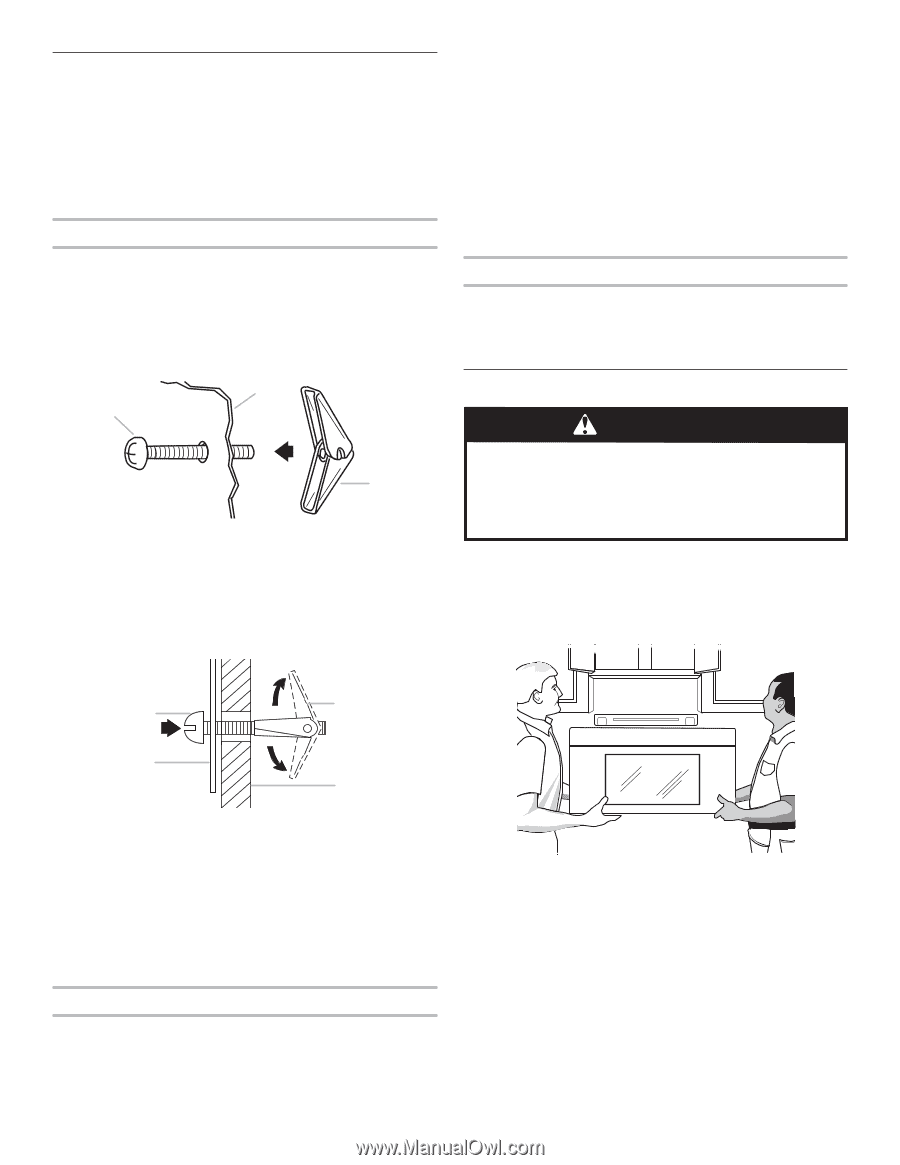
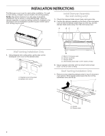
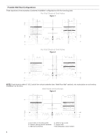
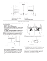
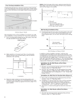
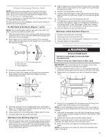
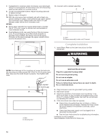
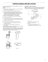
Attach Mounting Plate to Wall NOTE: Secure the mounting plate to the wall at both end holes drilled into the wall studs and/or drywall using either 3/16 - 24 x 3" (7.6 cm) round-head bolts and toggle nuts or 1/4" x 2" (0.6 cm x 5.1 cm) lag screws. Refer to illustrations in "Possible Wall Stud Configurations" in the "Locate Wall Stud(s)" section. For fast wall and roof vent installation, see the quick reference guide on the mounting plate. No Wall Studs at End Holes (Figures 1 and 2) NOTE: The mounting plate must be secured to the wall on at least 1 wall stud as well as at both ends. 1. With the support tabs of the mounting plate facing forward, insert 3/16-24 x 3" (7.6 cm) round-head bolts through both end holes of mounting plate. 2. Start toggle nuts on bolts from the back of the mounting plate. Leave enough space for the toggle nuts to go through the wall and to open. B A C A. 3/16 - 24 x 3" (7.6 cm) round-head bolt B. Mounting plate C. Spring toggle nut 3. Position mounting plate on the wall. 4. Push the 2 bolts with toggle nuts through the drywall and finger tighten the bolts to make sure toggle nuts have opened against drywall. 2. Start a toggle nut on the bolt from the back of the mounting plate. Leave enough space for the toggle nut to go through the wall and to open. 3. Position mounting plate on the wall. 4. Push the bolt with toggle nut through the drywall and finger tighten the bolt to make sure toggle nut has opened against drywall. 5. Insert a lag screw into the remaining end hole. 6. If installing on a second wall stud, insert a lag screw into the other hole drilled in Step 2 of "Installation for Wall Stud at One End Hole" in the "Drill Holes in Rear Wall" section. Check alignment of mounting plate, making sure it is level. 7. Securely tighten the lag screw(s) and bolt. Wall Studs at Both End Holes (Figure 4) 1. Position mounting plate on the wall. 2. Insert lag screws into both end holes. 3. Check alignment of mounting plate, making sure it is level. 4. Securely tighten the lag screws. Install the Microwave Oven WARNING Excessive Weight Hazard Use two or more people to move and install microwave oven. Failure to do so can result in back or other injury. IMPORTANT: The control side of the microwave oven is the heavy side. Handle the microwave oven gently. 1. Place a washer on each 1/4-20 x 3" (7.6 cm) flat-head bolt and place inside upper cabinet near the 3/8" (9.5 mm) holes. 2. Make sure the microwave oven door is closed and taped shut. A C B D A. 3/16 - 24 x 3" (7.6 cm) round-head bolt B. Mounting plate C. Spring toggle nut D. Drywall 5. Insert lag screw(s) into the hole(s) drilled into wall stud(s) in Step 2 of "Installation for No Wall Studs at End Holes" in the "Drill Holes in Rear Wall" section. 6. Check alignment of mounting plate, making sure it is level. 7. Securely tighten all lag screws and bolts. Wall Stud at One End Hole (Figure 3) 1. With the support tabs of the mounting plate facing forward, insert a 3/16-24 x 3" (7.6 cm) round-head bolt through the end hole that fits over the 5/8" (1.6 cm) hole drilled in Step 3 of "Installation for Wall Stud at One End Hole" in the "Drill Holes in Rear Wall" section. 3. Using 2 or more people, lift microwave oven and hang it on support tabs at the bottom of mounting plate. NOTE: To avoid damage to the microwave oven, do not grip or use the door or door handle while the microwave oven is being handled. 4. With front of microwave oven still tilted, thread power supply cord through the power supply cord hole in the bottom of the upper cabinet. 5. Rotate microwave oven up toward upper cabinet. NOTE: If venting through the wall, make sure the damper assembly fits easily into the vent in the wall cutout. 6. Push microwave oven against mounting plate and hold in place. NOTE: If microwave oven does not need to be adjusted, skip steps 7 through 9. 9
-
 1
1 -
2
-
3
-
 4
4 -
 5
5 -
 6
6 -
 7
7 -
 8
8 -
 9
9 -
 10
10 -
 11
11 -
 12
12
 |
 |