Yamaha 6FX Owner's Manual - Page 19
Front & Rear Panels, Channel Control - mg16 16 channel mixer
 |
View all Yamaha 6FX manuals
Add to My Manuals
Save this manual to your list of manuals |
Page 19 highlights
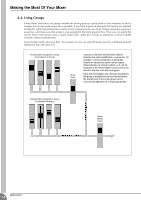
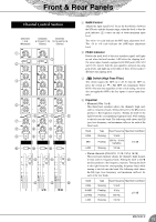
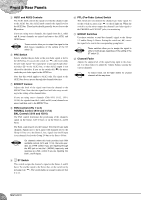
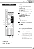
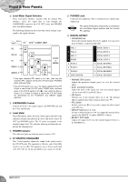
Front & Rear Panels Channel Control Section Channels 1 to 8 (Monaural) Channels Channels 9/10 and 11/12 13/14 and 15/16 (Stereo) (Stereo) 1 3 2 4 5 6 6 6 7 7 7 8 8 8 9 9 9 0 0 0 A A A B B B 1 GAIN Control Adjusts the input signal level. To get the best balance between the S/N ratio and the dynamic range, adjust the level so that the peak indicator (2) comes on only at about maximum input level. The -60 to -16 scale indicates the MIC-input adjustment level. The -34 to +10 scale indicates the LINE-input adjustment level. 2 PEAK Indicator Detects the peak level of the post-equalizer signal, and lights up red when the level reaches 3 dB below the clipping level. On stereo input channels equipped with XLR jacks (CHs 9/10 and 11/12), detects both the post-equalizer and post-mic-amp peak levels, and lights up red if either of these levels reaches 3 dB below the clipping level. 3 Switch (High Pass Filter) This switch toggles the HPF on or off. To turn the HPF on, press the switch in ( ). The HPF cuts frequencies below 80 Hz. (But note that regardless of the switch setting, the mixer does not apply this HPF to the line inputs of stereo input chan- nels.) 4 Equalizer • Monaural (CHs 1 to 8) This three-band equalizer adjusts the channel's high, mid, and low frequency bands. Setting the knob to the position produces a flat frequency response. Turning the knob to the right boosts the corresponding frequency band, while turning to the left cuts the band. The following table shows the EQ type, base frequency, and maximum cut/boost for each of the three bands. Band HIGH MID LOW Type Base Frequency Maximum Cut/Boost Shelving 10 kHz Peaking 250 Hz - 5 kHz (variable) ±15 dB Shelving 100 Hz • Stereo channels (CHs 9/10, 11/12, 13/14, 15/16) This four-band equalizer adjusts the channel's high, hi-mid, lo-mid, and low frequency bands. Setting the knob to the position produces a flat frequency response. Turning the knob to the right boosts the corresponding frequency band, while turning to the left cuts the band. The following table shows the EQ type, base frequency, and maximum cut/boost for each of the four bands. Band HIGH HI-MID LO-MID LOW Type Base Frequency Maximum Cut/Boost Shelving 10 kHz Peaking Peaking 3 kHz 800 Hz ±15 dB Shelving 100 Hz MG16/6FX 19
-
 1
1 -
2
-
3
-
4
-
5
-
6
-
7
-
8
-
9
-
10
-
11
-
12
-
13
-
 14
14 -
 15
15 -
 16
16 -
 17
17 -
 18
18 -
 19
19 -
 20
20 -
 21
21 -
 22
22 -
 23
23 -
 24
24 -
25
-
26
-
27
-
28
-
29
-
30
-
31
-
32
 |
 |
