Yamaha 6FX Owner's Manual - Page 23
Rear Input/Output Channel Input Jacks, INSERT I/O Jacks, GROUP OUT 1 to 4 Jacks, ST OUT L
 |
View all Yamaha 6FX manuals
Add to My Manuals
Save this manual to your list of manuals |
Page 23 highlights
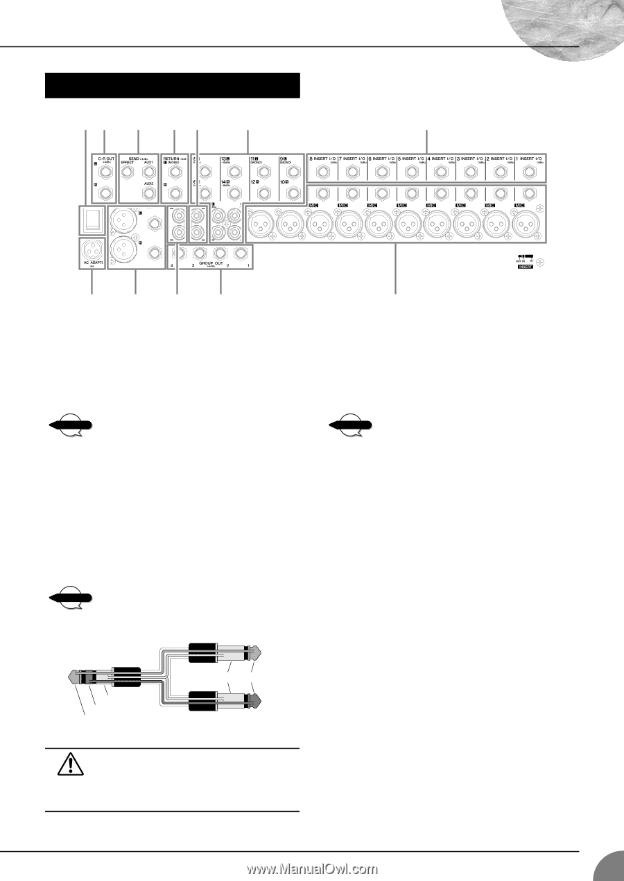
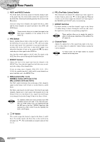
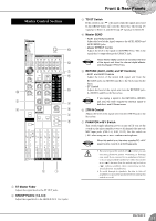
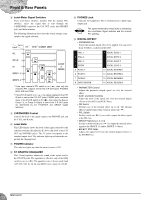
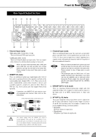
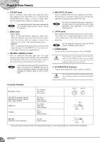
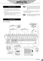
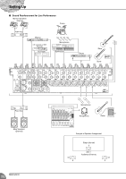
Rear Input/Output Section A6 7 8 0 3 Front & Rear Panels 2 B 594 1 Channel Input Jacks • MIC jacks (CHs 1 to 8, 9/10, 11/12) These are balanced XLR-type input jacks. • LINE jacks (CHs 1 to 8) These are balanced phone-type input jacks. You can connect either balanced or unbalanced phone plugs to these jacks. NOTE Where an input channel provides both a MIC jack and a LINE jack, you may use either one of these jacks but you may not use both at the same time. Please connect to only one of these jacks on each channel. 2 INSERT I/O Jacks These are unbalanced phone-type input/output jacks. Each of these jacks is positioned between the equalizer and fader of the corresponding input channel (CHs 1 to 8). These jacks can be used to independently connect these channels to devices such as graphic equalizers, compressors, and noise filters. These are TRS (tip, ring, sleeve) phone jacks that support bidirectional operation. NOTE Connection to an INSERT I/O jack requires a special separately-sold insertion cable such as illustrated below. To the input jack of the external processor To the INSERT I/O jack Sleeve Tip Sleeve Ring Tip To the output jack of the external processor The signal output from the INSERT I/O jacks is reverse-phased. This will not be a problem if connecting the jack to an effector. If using the jack to output to an external device, however, please be aware of possible phase conflicts with other signals. 1 3 Channel Input Jacks These are unbalanced input jacks. Two jack types are provided: phone type (CHs 9/10 to 15/16) and RCA pin type (CHs 13/14, 15/16). Use these jacks to input stereo signals, inputting the L signal(s) to the odd-numbered channel(s) and the R signal(s) to the even-numbered channel(s). NOTE • Where a channel provides both a phone jack and an RCA pin jack, you may use either one of these jacks but you may not use both at the same time. Please connect to only of these jacks on each channel. • The phone-type jacks for CH9/10 and 11/12 also support monaural input. Specifically, if you input only into the L(MONO) jack of either pair (while leaving the R jack empty), the mixer will propagate the same signal through both the L(MONO) and R inputs. 4 GROUP OUT (1 to 4) Jacks These are impedance-balanced phone-type output jacks that output the Group 1-2/3-4 signals. Use these jacks to connect to the input jacks of an MTR, external mixer, or other such device. 5 ST OUT (L, R) Jacks These jacks output the mixed signal whose level is adjusted by the ST fader in the Master Control section. Output is in stereo (L and R). You use these jacks, for example, to connect to the power amplifier driving your main speakers. • XLR jacks XLR-type balanced output jacks. • Phone jacks TRS phone-type balanced output jacks. MG16/6FX 23
-
 1
1 -
2
-
3
-
4
-
5
-
6
-
7
-
8
-
9
-
10
-
11
-
12
-
13
-
14
-
15
-
16
-
17
-
 18
18 -
 19
19 -
 20
20 -
 21
21 -
 22
22 -
 23
23 -
 24
24 -
 25
25 -
 26
26 -
 27
27 -
 28
28 -
29
-
30
-
31
-
32
 |
 |