Yamaha A-S1100 Owners Manual
Yamaha A-S1100 Manual
 |
View all Yamaha A-S1100 manuals
Add to My Manuals
Save this manual to your list of manuals |
Yamaha A-S1100 manual content summary:
- Yamaha A-S1100 | Owners Manual - Page 1
AB Integrated Amplifier OWNER'S MANUAL - Yamaha A-S1100 | Owners Manual - Page 2
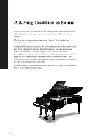
apply this very same concept to the manufacture of our audio products. The technician performs exhaustive listening tests and every component is considered, in order to finally achieve the ideal sound. Yamaha's tradition of audio quality stretches back over 125 years, and continues to live on in all - Yamaha A-S1100 | Owners Manual - Page 3
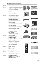
Monitor Speaker CA-1000 Integrated Amplifier Featuring A-Class operation, the CA-1000 set the standard for integrated amplifiers. NS-690 Natural A-1 Integrated Amplifier PX-2 Turntable Yamaha's first straight arm turntable. NS-690 B-1 PX-2 B-6 B-6 Power Amplifier Pyramid-shaped power amplifier. - Yamaha A-S1100 | Owners Manual - Page 4
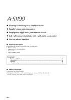
phono amplifier ■ Supplied accessories Please check that you have received all of the following parts. • Remote control • Batteries (AAA, R03, UM-4) (×2) • Power cable • SAFETY BROCHURE Contents Controls and functions...6 Connections...16 Appendix...24 Troubleshooting...28 ■ About this manual - Yamaha A-S1100 | Owners Manual - Page 5
Controls and functions In this chapter, you will learn the controls and functions of A-S1100. 5 En - Yamaha A-S1100 | Owners Manual - Page 6
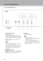
CONTROLS AND FUNCTIONS Controls and functions ■ Front panel (pages 6 to 9) 1 23 4 5 67 8 9 1 STANDBY/ON, OFF switch Turns on or off this unit. STANDBY/ON (upper position): With this switch position, pressing the p AMP key on the remote control toggles the power between STANDBY and ON. OFF ( - Yamaha A-S1100 | Owners Manual - Page 7
4 SPEAKERS selector Turns on or off the sets of speakers connected to the SPEAKERS L/R CH A and/or B terminals on the rear panel, as follows. OFF: Both sets of speakers are off. A/B: The set of speakers connected to the A or B terminals is on. A+B BI-WIRING: Both sets of speakers are on. 5 METER - Yamaha A-S1100 | Owners Manual - Page 8
Controls and functions ■ Front panel (pages 6 to 9) 0 A 0 Remote control sensor Receives signals from the remote control. A INPUT selector/indicator Selects the input source. The indicator of the input source selected with the INPUT selector lights. The audio signals of the selected input source - Yamaha A-S1100 | Owners Manual - Page 9
VOLUME control does not affect when you select MAIN DIRECT as the input source. Adjust the volume level using the volume control on the external amplifier connected to the MAIN IN jacks. 9 En - Yamaha A-S1100 | Owners Manual - Page 10
same channel signal as the SPEAKERS L/R CH terminals. • When you connect a stereo cable to the PRE OUT jacks to drive the speakers using an external amplifier, it is not necessary to use the SPEAKERS L/R CH terminals. • The signal output at the PRE OUT jacks are affected by the BASS and TREBLE - Yamaha A-S1100 | Owners Manual - Page 11
fixed. Adjust the volume level using the volume control on the external amplifier connected to the MAIN IN jacks when you select MAIN DIRECT as the page 20. D SYSTEM CONNECTOR Use this connector to connect a product testing device for servicing. E AC IN inlet Use this inlet to plug in the supplied - Yamaha A-S1100 | Owners Manual - Page 12
to the CD jacks. TUNER: Selects the tuner connected to the TUNER jacks. 4 Tuner control buttons Control functions of Yamaha tuner. Refer to the owner's manual of your tuner for details. Note Certain Yamaha tuners may not respond to some of these control keys on the remote control. MUTE 7 12 En - Yamaha A-S1100 | Owners Manual - Page 13
player control keys Control various functions of Yamaha CD player. Refer to the owner's manual of your CD player for details. p you select MAIN DIRECT as the input source. Adjust the volume level on the external amplifier connected to the MAIN IN jacks. 7 MUTE key Reduces the current volume level by - Yamaha A-S1100 | Owners Manual - Page 14
Controls and functions ■ Installing batteries in the remote control 1 Remove the battery compartment cover. 2 Insert the two batteries (AAA, R03, UM-4) according to the polarity markings (+ and -) on the inside of the battery compartment. ■ Operating range of the remote control Approximately 6 m - Yamaha A-S1100 | Owners Manual - Page 15
Connections In this section, you will make connections between A-S1100, speakers, and source components. - Yamaha A-S1100 | Owners Manual - Page 16
speakers, and if the polarity of the speaker connections is incorrect, the sound will be unnatural and lack bass. Also, refer to the owner's manual for each of your components. • Use RCA unbalanced cables to connect other components except speakers. • Connect your turntable to the GND terminal to - Yamaha A-S1100 | Owners Manual - Page 17
subwoofer Speakers A (L channel) +- -+ CD recorder, tape deck, etc. Preamplifier, AV receiver, etc. Speakers B (L channel) Notes • Because the power amplifier of A-S1100 is of the floating balanced type, the following types of connections are not possible. Fig. 1 - Connecting with the left - Yamaha A-S1100 | Owners Manual - Page 18
Connections ■ Connecting the speakers 1 Remove approximately 10 mm of insulation from the end of each speaker cable and twist the exposed wires of the cable together to prevent short circuits. ■ Connecting the banana plug (Except for Europe models) First, tighten the knob and then insert the - Yamaha A-S1100 | Owners Manual - Page 19
the AC IN inlet when all connections are complete, and then plug in the power cable to the AC outlet. Rear panel of A-S1100 Rear panel of A-S1100 Speaker SPEAKERS R CH + A + B Supplied power cable Caution To use the bi-wire connections, the impedance of each speaker must be 8 or higher - Yamaha A-S1100 | Owners Manual - Page 20
using the supplied remote control located in another room. Rear panel of A-S1100 TRIGGER IN REMOTE SYSTEM CONNECTOR IN OUT ■ Remote connection between Yamaha components When you have another Yamaha component supporting remote connection, as this unit does, an infrared transmitter is not - Yamaha A-S1100 | Owners Manual - Page 21
). Connect the PRE OUT jacks and the TRIGGER OUT jack of the Yamaha AV receiver to this unit as illustrated below: Rear panel of A-S1100 MAIN IN TRIGGER IN RCA stereo cable Monaural mini-plug cable PRE OUT TRIGGER OUT Yamaha AV receiver, etc. with PRE OUT and TRIGGER OUT jacks When the - Yamaha A-S1100 | Owners Manual - Page 22
22 En - Yamaha A-S1100 | Owners Manual - Page 23
Appendix In this section, you will find technical specifications for A-S1100. 20kHz 1kHz 20Hz 20Hz 1kHz 20kHz - Yamaha A-S1100 | Owners Manual - Page 24
Characteristics BASS Boost/Cut (50 Hz 9 dB Turnover Frequency 350 Hz TREBLE Boost/Cut (20 kHz 9 dB Turnover Frequency 3.5 kHz GENERAL • Power Supply [U.S.A and Canada models AC 120 V, 60 Hz [Taiwan model AC 110 V, 60 Hz [China model AC 220 V, 50 Hz [Korea model AC 220 V, 60 Hz [Australia - Yamaha A-S1100 | Owners Manual - Page 25
FOR MM EQ AMP FOR After Vol Amp FOR INPUT AMP FOR VOLUME FOR HP AMP INDEPENDENT REGULATED POWER SUPPLY (for AUDIO) MAIN TRANSFORMER Log amplifier Peak / VU DRIVER FLOATING POWER SUPPLY Rch Rch Lch METOR MOTOR VOL RELAY IR REMOTE SPEAKERS METER STANDBY/ON OFF/A/B/A+B OFF/PEAK/VU VOLUME - Yamaha A-S1100 | Owners Manual - Page 26
Appendix ■ Tone control characteristics Relative Level (dB) 14 12 10 8 6 4 2 0 -2 -4 -6 -8 -10 -12 -14 10 20 30 50 100 200 300 500 1k 2k 3k 5k 10k 20k 30k 50k 100k Frequency (Hz) ■ Total harmonic distortion 1 0.5 0.3 0.2 THD + N Ratio (%) 0.1 0.05 0.03 0.02 0.01 0.005 0. - Yamaha A-S1100 | Owners Manual - Page 27
■ Total harmonic distortion (PHONO) THD + N Ratio (%) 10 5 3 2 1 0.5 0.3 0.2 0.1 0.05 0.03 20Hz 0.02 1kHz 20kHz 0.01 0.005 0.003 0.002 0.001 0.0005 0.0003 0.0002 0.0001 100µ 200µ 500µ 1m 2m 5m 10m 20m 50m 100m 200m 500m 1 2 Generator Level (Vrms) 27 En - Yamaha A-S1100 | Owners Manual - Page 28
Troubleshooting Refer to the chart below if this unit does not function properly. If the problem you are experiencing is not listed below or if the instructions below do not help, turn off this unit, disconnect the power cable, and contact the nearest authorized Yamaha dealer or service amplifier or - Yamaha A-S1100 | Owners Manual - Page 29
connection from the turntable to the GND terminal. The power of this unit is turned off. Remedy Connect the audio cable plugs firmly. If the problem persists, the cables may be defective. Connect the turntable to the GND terminal of this unit. Turn on the power of this unit. Incorrect setting - Yamaha A-S1100 | Owners Manual - Page 30
- Yamaha A-S1100 | Owners Manual - Page 31
- Yamaha A-S1100 | Owners Manual - Page 32
© 2015 Yamaha Corporation Printed in Malaysia ZQ25570
-
 1
1 -
 2
2 -
 3
3 -
 4
4 -
 5
5 -
 6
6 -
 7
7 -
8
-
9
-
10
-
11
-
12
-
13
-
14
-
15
-
16
-
17
-
18
-
19
-
20
-
21
-
22
-
23
-
24
-
25
-
26
-
27
-
28
-
29
-
30
-
31
-
32
 |
 |

AB
Integrated Amplifier
OWNER’S MANUAL