Yamaha A-S1100 Owners Manual - Page 11
MAIN IN jacks, AUTO POWER STANDBY switch, TRIGGER IN jack, REMOTE IN/OUT jacks, SYSTEM CONNECTOR
 |
View all Yamaha A-S1100 manuals
Add to My Manuals
Save this manual to your list of manuals |
Page 11 highlights
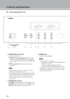
A B CD 2 E F 0 MAIN IN jacks Use these jacks to connect an external component equipped with a volume control. y When you select MAIN DIRECT as the input source, the volume level is fixed. Adjust the volume level using the volume control on the external amplifier connected to the MAIN IN jacks when you select MAIN DIRECT as the input source. For the connection to the MAIN IN jacks, see pages 16 and 17. A AUTO POWER STANDBY switch ON: The unit enters STANDBY mode automatically if not operated for 8 hours. OFF: The unit does not enter STANDBY mode automatically. B TRIGGER IN jack Use this jack to connect an external component for the trigger function. For details on the connection, see page 21. C REMOTE IN/OUT jacks Use these jacks to connect an external component for remote control. For details on the connection, see page 20. D SYSTEM CONNECTOR Use this connector to connect a product testing device for servicing. E AC IN inlet Use this inlet to plug in the supplied power cable. For details on the connection, see page 19. F Foot If this unit is unstable, you can adjust the foot height by rotating it. 11 En
-
 1
1 -
2
-
3
-
4
-
5
-
 6
6 -
 7
7 -
 8
8 -
 9
9 -
 10
10 -
 11
11 -
 12
12 -
 13
13 -
 14
14 -
 15
15 -
 16
16 -
17
-
18
-
19
-
20
-
21
-
22
-
23
-
24
-
25
-
26
-
27
-
28
-
29
-
30
-
31
-
32
 |
 |
