Yamaha A-S2100 A-S2100 Owners Manual - Page 10
Rear panel, SPEAKERS L/R CH terminals
 |
View all Yamaha A-S2100 manuals
Add to My Manuals
Save this manual to your list of manuals |
Page 10 highlights
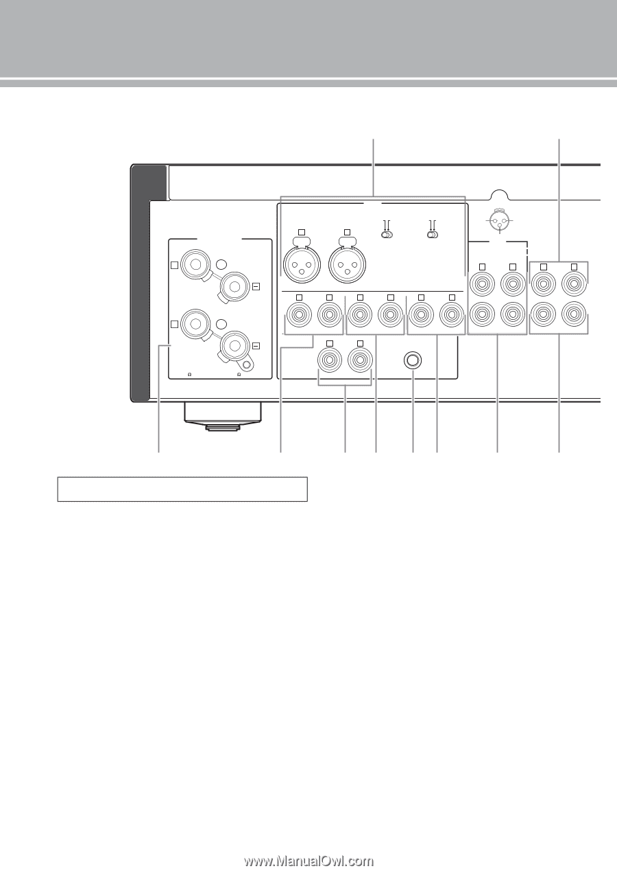
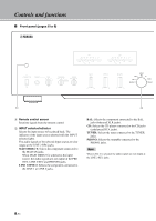
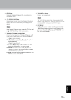
Controls and functions ■ Rear panel 1 2 SPEAKERS R CH + A + B A OR B:4 MIN. /SPEAKER A+B:8 MIN. /SPEAKER INPUT ATTENUATOR PHASE NORMAL (EIA) BYPASS ATT. NORMAL INV. (-6dB) + HOT 21 3 GND R L - COLD LINE2 R REC L R PRE OUT L BAL R L R L R L TUNER R PHONO CD L LINE 1 GND PB MAIN IN 3 4 5 6 78 9 0 See page 16 for connection information. 1 BAL (balanced) input jacks One set of balanced input jacks is provided. Set the ATTENUATOR selector and PHASE selector appropriately for the playback component that is connected. For details on these switches, refer to page 20. 2 PRE OUT jacks y • The PRE OUT jacks output the same channel signal as the SPEAKERS L/R CH terminals. • When you connect a stereo cable to the PRE OUT jacks to drive the speakers using an external amplifier, it is not necessary to use the SPEAKERS L/R CH terminals. • The signal output at the PRE OUT jacks are affected by the BASS and TREBLE control settings. 3 SPEAKERS L/R CH terminals 4 TUNER input jacks 5 PHONO input jacks 6 CD input jacks 7 GND (Ground) terminal 8 LINE 1 input jacks 9 LINE 2 jacks PB (playback) input jacks and REC (recording) output jacks are provided. 0 MAIN IN jacks Use these jacks to connect an external component equipped with a volume control. y When you select MAIN DIRECT as the input source, the volume level is fixed. Adjust the volume level using the volume control on the external amplifier connected to the MAIN IN jacks when you select MAIN DIRECT as the input source. For the connection to the MAIN IN jacks, see pages 16 and 17. 10 En
-
 1
1 -
2
-
3
-
4
-
 5
5 -
 6
6 -
 7
7 -
 8
8 -
 9
9 -
 10
10 -
 11
11 -
 12
12 -
 13
13 -
 14
14 -
 15
15 -
16
-
17
-
18
-
19
-
20
-
21
-
22
-
23
-
24
-
25
-
26
-
27
-
28
-
29
-
30
-
31
-
32
-
33
-
34
-
35
-
36
-
37
-
38
-
39
-
40
-
41
-
42
-
43
-
44
-
45
-
46
-
47
-
48
-
49
-
50
-
51
-
52
-
53
-
54
-
55
-
56
-
57
-
58
-
59
-
60
 |
 |