Yamaha A-S2100 A-S2100 Owners Manual - Page 17
English
 |
View all Yamaha A-S2100 manuals
Add to My Manuals
Save this manual to your list of manuals |
Page 17 highlights
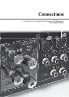
External amplifier or active subwoofer Speakers A (L channel) +- TOR TT. -6dB) PHASE NORMAL INV. NORMAL (EIA) + HOT 21 3 GND - COLD LINE2 R REC L R PRE OUT L R L LINE 1 GND PB MAIN IN AUTO POWER STANDBY ON OFF SPEAKERS L CH A TRIGGER IN REMOTE SYSTEM CONNECTOR IN OUT + B + A OR B: 4 MIN. /SPEAKER A+B:8 MIN. /SPEAKER AC IN -+ CD recorder, tape deck, etc. Preamplifier, AV receiver, etc. Notes • Because the power amplifier of A-S2100 is of the floating balanced type, the following types of connections are not possible. Fig. 1 - Connecting with the left channel "-" terminal and the right channel "-" terminal as well as "+" terminals (Fig. 1). + L - Connecting with the left channel "-" terminal and the right channel "-" terminal - inverted (cross connection, Fig. 2). - Deliberately connecting with the left/right channel "-" terminals and metal part - on the rear panel of this unit, as well as accidentally touching them. R • Do not connect your active subwoofer to the SPEAKERS L/R CH terminal. + Connect it to the PRE OUT jacks of this unit. • Do not connect a component with no volume control, such as a CD player, to the MAIN IN jacks, as the volume level of the signals input to the MAIN IN jacks is fixed. If such equipment is connected, a sound may burst, and the unit and/or speaker may be damaged. + - Speakers B (L channel) Fig. 2 + L - R 17 En English
-
 1
1 -
2
-
3
-
4
-
5
-
6
-
7
-
8
-
9
-
10
-
11
-
 12
12 -
 13
13 -
 14
14 -
 15
15 -
 16
16 -
 17
17 -
 18
18 -
 19
19 -
 20
20 -
 21
21 -
 22
22 -
23
-
24
-
25
-
26
-
27
-
28
-
29
-
30
-
31
-
32
-
33
-
34
-
35
-
36
-
37
-
38
-
39
-
40
-
41
-
42
-
43
-
44
-
45
-
46
-
47
-
48
-
49
-
50
-
51
-
52
-
53
-
54
-
55
-
56
-
57
-
58
-
59
-
60
 |
 |
