Yamaha CLP-320 Owner's Manual - Page 35
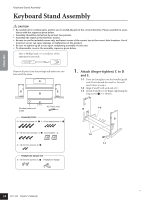
Attach B., Securely tighten the screws on C, that were attached in Step 1-3., Mount A., Secure A.
 |
View all Yamaha CLP-320 manuals
Add to My Manuals
Save this manual to your list of manuals |
Page 35 highlights
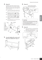
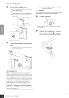
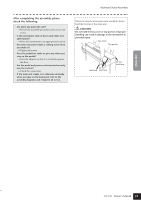
33 ENGLISH L R R 2. Attach B. Depending on the model of Clavinova you purchased, the surface color of one side of B may be different from the other side. In this case, position B so that the side of the surface color similar to D and E faces the player. 2-1 Place the lower side of B on each foot of D and E, then attach the upper side to D and E. 2-2 Attach the top of B to D and E by fingertightening the thin screws 3 (4 × 12mm). 2-3 While pushing the lower part of D and E from outside, secure the bottom ends of B using two tapping screws 4 (4 × 20mm). 2-4 Insert the other two tapping screws 4 (4 × 20mm) into the other two screw holes to secure B. 2-5 Securely tighten the screws on the top of B that were attached in Step 2-2. E 2-2, 2-5 2-1 Place the bottom ends of the rear panel on each foot. B D 2-3 2-4 2-3 3. Securely tighten the screws on C that were attached in Step 1-3. Keyboard Stand Assembly 4. Mount A. Be sure to place your hands at least 10 cm from either end of the main unit when positioning it. A At least E 10 cm D B CAUTION • Fingers can become pinched between the main unit and the rear or side panels, be extra careful so as not to drop the main unit. • Do not hold the keyboard in any position other than the position shown in the illustration. 5. Secure A. 5-1 Adjust the position of A so that the left and right ends of A will project beyond D and E equally when seen from the front. 5-2 Secure A by tightening the short screws 2 (6 × 16mm) from the front. 5-1 A Projection of A B C 3 A 5-2 CLP-320 Owner's Manual 35
-
 1
1 -
2
-
3
-
4
-
5
-
6
-
7
-
8
-
9
-
10
-
11
-
12
-
13
-
14
-
15
-
16
-
17
-
18
-
19
-
20
-
21
-
22
-
23
-
24
-
25
-
26
-
27
-
28
-
29
-
 30
30 -
 31
31 -
 32
32 -
 33
33 -
 34
34 -
 35
35 -
 36
36 -
 37
37 -
 38
38 -
 39
39 -
 40
40 -
41
-
42
-
43
-
44
 |
 |
