Yamaha CVP-600 Reference Manual - Page 60
CVP-600: Assembly, CVP-600: Zusammenbau
 |
View all Yamaha CVP-600 manuals
Add to My Manuals
Save this manual to your list of manuals |
Page 60 highlights
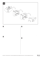
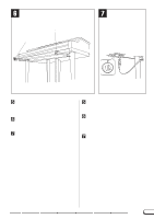
1 q Front leg A q Vorderes Standbein A q Pied avant A q Pata frontal A A D C B q Front leg B q Vorderes Standbein B q Pied avant B q Pata frontal B q Rear leg C q Hinteres Standbein C q Pied arrière C q Pata trasera C q Pedal box D q Pedalkasten D q Pédalier D q Caja de pedales D 5 x 20 mm long screws Lange Schrauben (5 x 20 mm) Vis longue 5 x 20 mm Tornillos largos de 5 x 20 mm x 20 q Cord holders q Kabelhalter x 2 q Serre-câble q Soportes de cable q AC power cord q Netzkabel q Cordon d'alimentation q Cable de alimentación de CA CVP-600: Assembly • Be careful not to confuse parts, and be sure to install all parts in the correct direction. Please assemble in accordance with the sequence given below. • Assembly should be carried out by at least two persons. • Be sure to use the correct screw size, as indicated above. Use of incorrect screws can cause damage. • Be sure to tighten up all screws upon completing assembly of each unit. • The entire package must be turned over during assembly, so select an area that is large enough for the unpacking and assembly operation. Z Open the carton and remove the parts from the upper level. Referring to the illustration, make sure that you have all the required parts. • A bench may be supplied or optional, depending on the location in which the instrument was purchased. X Attach the three legs (A, B, C). Use scissors or a cutter to remove the packing material in which the main unit is wrapped. Then attach the legs to the bottom of the main unit using four 5 x 20 mm long screws per leg. Please refer to the illustration carefully when attaching the legs, to ensure that the positions of the (A) and (B) legs are not reversed. Also make sure that there is minimum space between the (A) and (B) leg flanges and the metal frame on the bottom of the main unit (the screws which attach the legs to this frame will be installed later, in step N). 38 CVP-98/96/600 CVP-600: Zusammenbau • Achten Sie darauf, die Teile nicht zu verwechseln, und installieren Sie alle Teile in der richtigen Ausrichtung. Gehen Sie beim Zusammenbau bitte in der angegebenen Reihenfolge vor. • Die Montage sollte von mindestens zwei Personen vorgenommen werden. • Achten Sie darauf, die richtige Schraubengröße zu verwenden, wie es oben gezeigt ist. Die Verwendung der falschen Schrauben kann zu Schäden führen. • Achten Sie während der Montage darauf, bei jedem Arbeitsgang alle Schrauben festzuziehen. • Das Instrument wird im Karton zusammengebaut und muß abschließend zum Aufstellen umgedreht werden. Achten Sie darauf, daß ausreichend Platz zum Auspacken und Aufstellen vorhanden ist. Z Den Karton öffnen und die Teile der ober- sten Lage herausnehmen. Prüfen Sie anhand der Abbildung, ob die Teile vollzählig vorhanden sind. • Je nach Vertriebsland wird eine Sitzbank entweder standardmäßig mitgeliefert oder ist als Sonderzubehör erhältlich. X Die drei Standbeine (A, B und C) montieren. Entfernen Sie das Verpackungsmaterial an der Unterseite des Instruments mit einer Schere oder einem anderen Schneidwerkzeug. Schrauben Sie dann die drei Standbeine mit jeweils vier langen Schrauben (5 x 20 mm) an das Instrument. Richten Sie sich bei der Montage der Standbeine bitte nach der Abbildung - die vorderen Standbeine (A und B) dürfen nicht vertauscht werden. Achten Sie auch darauf, daß zwischen den Ansätzen an den vorderen Standbeinen (A und B) und dem Metallrahmen an der Unterseite des Instruments ein möglichst kleiner Zwischenraum verbleibt (die Standbeine werden an späterer Stelle, in Schritt N, mit diesem Rahmen verschraubt ).
-
 1
1 -
2
-
3
-
4
-
5
-
6
-
7
-
8
-
9
-
10
-
11
-
12
-
13
-
14
-
15
-
16
-
17
-
18
-
19
-
20
-
21
-
22
-
23
-
24
-
25
-
26
-
27
-
28
-
29
-
30
-
31
-
32
-
33
-
34
-
35
-
36
-
37
-
38
-
39
-
40
-
41
-
42
-
43
-
44
-
45
-
46
-
47
-
48
-
49
-
50
-
51
-
52
-
53
-
54
-
 55
55 -
 56
56 -
 57
57 -
 58
58 -
 59
59 -
 60
60 -
 61
61 -
 62
62 -
 63
63 -
 64
64 -
 65
65 -
66
-
67
-
68
-
69
-
70
-
71
-
72
-
73
-
74
-
75
 |
 |
