Yamaha EMX512SC Owner's Manual - Page 21
INPUT A and INPUT B jacks Channels 1 to 4, COMP knob EMX512SC and EMX312SC only - 12 channel powered mixer
 |
UPC - 086792831329
View all Yamaha EMX512SC manuals
Add to My Manuals
Save this manual to your list of manuals |
Page 21 highlights
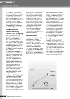
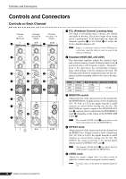
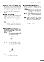
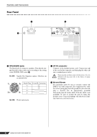
Controls and Connectors 6 COMP knob (EMX512SC and EMX312SC only) This knob adjusts the level of compression applied to the channel. As the knob is turned to the right, the mixer automatically raises the compression ratio while adjusting the output gain accordingly. The result is a narrower, more even dynamic range, as louder signals are softened while the overall level is boosted. Avoid setting the knob too high, however, as excess compression may lead to howling. 7 LINE/MIC switch (Channels 1 to 4) Set this switch to match the type of input signal you are supplying-either a mic-level (low level) signal or a line-level (high level) signal. Set the switch to LINE ( ) if you are connecting a line-level source, such as a keyboard or audio device. Set it to MIC ( ) if you are connecting up a microphone or other mic-level source. To avoid damage to speakers, be sure to turn off the power to the EMX itself and to any other power amplifiers and power speakers before setting this switch to LINE or MIC. We also recommend that you turn all output controls (LEVEL knobs, MASTER knobs, etc.) to minimum settings before operating the switch, to avoid risk of loud noises that could cause hearing loss or device damage. 8 INPUT A and INPUT B jacks (Channels 1 to 4) You can connect an input source to either jack. Be sure to set the LINE/MIC switch 7 to match the type of device you are connecting. INPUT A: TRS phone-type balanced line input (T: hot, R: cold, S: ground). Accepts both balanced and unbalanced line input. R: Cold (-) 9 LINE and MIC jacks (Channels 5/6 to 11/12) These jacks accept stereo inputs. Use these to connect up stereo output devices, such as stereo synthesizers and CD players. LINE jacks: Unbalanced stereo inputs. On channel pairs 5/6 and 7/8 these are phone jacks; on channel pairs 9/10 and 11/12 they are RCA pin jacks. MIC jack: XLR balanced stereo mic-level input jack. If you are connecting a condenser microphone, be sure to turn the PHANTOM switch P to its ON position. NOTE • If you wish, you may use the channel pair's LINE and MIC jacks together at the same time. But note that the levels cannot be adjusted independently. • Signals into LINE L and LINE R jacks are sent independently to the corresponding MAIN L and R buses. • The signal into a MIC jack is sent in equal levels to the MAIN L and MAIN R buses. S: Ground T: Hot (+) INPUT B: XLR balanced mic input (1: ground, 2: hot, 3: cold). If you are connecting a condenser microphone, be sure to turn the PHANTOM switch P to its ON position. Cold (-) Ground Hot (+) NOTE • You cannot use both jacks at the same time. • The signal into an INPUT jack is sent in equal levels to the MAIN L and MAIN R buses. EMX512SC/EMX312SC/EMX212S 21
-
 1
1 -
2
-
3
-
4
-
5
-
6
-
7
-
8
-
9
-
10
-
11
-
12
-
13
-
14
-
15
-
 16
16 -
 17
17 -
 18
18 -
 19
19 -
 20
20 -
 21
21 -
 22
22 -
 23
23 -
 24
24 -
 25
25 -
 26
26 -
27
-
28
-
29
-
30
-
31
-
32
-
33
-
34
-
35
-
36
 |
 |