Yamaha EMX512SC Owner's Manual - Page 32
Specifications, General Specifications - phantom power
 |
UPC - 086792831329
View all Yamaha EMX512SC manuals
Add to My Manuals
Save this manual to your list of manuals |
Page 32 highlights
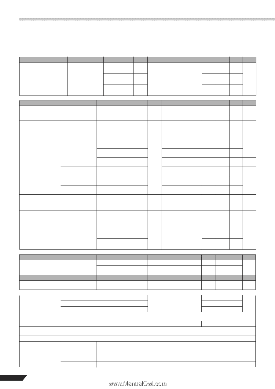
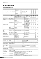
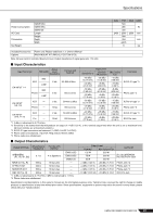
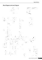
Specifications Specifications ■ General Specifications Output EMX512SC Maximum Output Power SPEAKERS OUT EMX312SC EMX212S RL Conditions 4 Ω 8 Ω 4 Ω Both ch drive, 1 kHz, 8 Ω THD+N =< 0.5% 4 Ω 8 Ω US AU EU UNIT 500 500 500 350 350 320 300 300 300 MIN W 190 190 180 220 220 220 130 130 130 Frequency Response Maximum Voltage Gain@ 1 kHz Input CH INPUT 1-11/12 CH 1-4 INPUT B, CH 5/6-11/12 MIC Output MAIN OUT, MONITOR OUT, EFFECT OUT, REC OUT SPEAKERS OUT MAIN OUT, MONITOR OUT MAIN OUT CH 1-4 INPUT B, CH 5/6-11/12 MIC MONITOR OUT EFFECT OUT Gain Error @ 1 kHz It measures in each CH unit. REC OUT CH 1-4 INPUT A MAIN OUT CH 5/6-7/8 LINE (Phone) MAIN OUT CH 9/10-11/12 LINE (Pin) MAIN OUT Total Harmonic Distortion It measures in each CH unit. (THD+N) CH INPUT 1-11/12 MAIN OUT, MONITOR OUT, EFFECT OUT, REC OUT CH 1-4 INPUT B, Hum & Noise CH 5/6-11/12 MIC (20 Hz-20 kHz) It measures in each CH unit. EIN=Equivalent Input Noise CH INPUT 1-11/12 MAIN OUT MAIN OUT, MONITOR OUT, EFFECT OUT Residual Output Noise (20 Hz-20 kHz) MAIN OUT L, R - MONITOR OUT SPEAKERS OUT RL Conditions 10 kΩ CH1-4 MIC/LINE: MIC 20 Hz-20 kHz, 0 dB 4 Ω @ 1 kHz 10 kΩ Rs=150 Ω CH1-4 MIC/LINE:MIC Input level:-60 dBu CH1-4 MIC/LINE:MIC Input level:-60 dBu CH1-4 MIC/LINE:MIC Input level:-60 dBu CH1-4 MIC/LINE:MIC 10 kΩ Input level:-60 dBu CH1-4 MIC/LINE:MIC Input level:-50 dBu MIC/LINE:MIC MIN -3.0 -3.0 2.0 2.0 -8.0 -12.0 2.0 TYP 0.0 0.0 65 4.0 4.0 -6.0 -10.0 4.0 MAX 1.0 1.0 6.0 6.0 -4.0 -8.0 6.0 UNIT dB dB dBu dBV Input level:-20 dBu 2.0 4.0 6.0 dBu Input level:-20 dBu 2.0 4.0 6.0 10 kΩ +14 dBu @ 20 Hz, 1 kHz, 20 kHz EIN, Rs=150 Ω CH1-4 MIC/LINE:MIC 10 kΩ Output Noise Rs=150 Ω CH1-4 MIC/LINE:MIC 10 kΩ Master control at minimum. 4 Ω 0.5 % -115 dBu -50 -90 -90 dBu -65 Crosstalk @ 1 kHz It measures in each CH unit. Phantom Voltage It measures in each CH unit. Input CH1-4 Output CH 1-4 INPUT B, CH 5/6-11/12 MIC Output Adjacent CH inputs MAIN OUT - - Conditions Input to Output (LEVEL controls: minimum) No load MIN TYP MAX UNIT -65 dB -65 MIN TYP MAX UNIT 14 15 16 V HIGH CH & ST CH Equalization MID LOW Turn over /roll-off frequency of 10 k (shelving) shelving :3dB below maximum variable level. 2.5 k (peaking) Hz ±15dB maximum 100 (shelving) Internal Digital Effect 16 programs Parameter control FOOT SW ON/OFF Level Meters 2 × 5-points LED level meter [MAIN(L,R)], 5-points LED level meter [MONITOR] +6, +3, 0, -5, -10 [dB] FCL Sensitivity Protection Input signal level => -75dBu: LED on, CH1-4 MIC/LINE:MIC B Input, CH 5/6-11/12 MIC Input Power Amplifier POWER switch on/off mute DC-fault :power supply shutdown /manual reset Thermal /heatsink temp => 90˚C:output mute /auto reset Vl limiter /RL =< 2 Clip limiter /THD Ω => 1 %, Indicator × 2 Power Supply Thermal /heatsink temp => 100˚C :power supply shutdown /manual reset 32 EMX512SC/EMX312SC/EMX212S
-
 1
1 -
2
-
3
-
4
-
5
-
6
-
7
-
8
-
9
-
10
-
11
-
12
-
13
-
14
-
15
-
16
-
17
-
18
-
19
-
20
-
21
-
22
-
23
-
24
-
25
-
26
-
 27
27 -
 28
28 -
 29
29 -
 30
30 -
 31
31 -
 32
32 -
 33
33 -
 34
34 -
 35
35 -
 36
36
 |
 |