Yamaha HS80M Owner's Manual - Page 10
MG-series Mixer Setup, Example: MG16/6FX, Digital Mixer Setup - stand
 |
UPC - 086792837536
View all Yamaha HS80M manuals
Add to My Manuals
Save this manual to your list of manuals |
Page 10 highlights
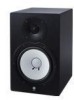
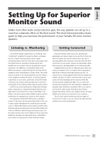
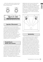
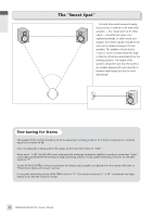
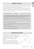
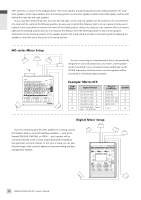
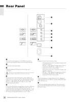
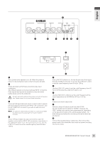
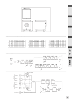
English 100° and 120°, as shown in the diagram above. The center speaker should be placed precisely midway between the main front speakers, at the same distance from the listening position as the other speakers (which means that ideally it will be a bit behind the main left and right speakers. As you may have deduced by now, the main left and right, center, and rear speakers are all located on the circumference of a circle with its center at the listening position. An easy way to get all the distances right is to use a piece of string cut or marked to the exact distance between the main left and right speakers. Attach the string to a mic stand or other convenient object at the listening position and use it to measure the distance from the listening position to each of the speakers. Stretched from the listening position to the speaker position the string will also provide a convenient guide for aligning the speakers so that they point directly at the listening position. MG-series Mixer Setup C L R DVD Player 6 Channel Line LS If you're connecting to a standard mixer that is not specifically designed for surround production, your main L and R speakers LFE can be connected to any convenient stereo output pair via the HS10W subwoofer, while the center and rear speakers will be connected to individual output channels. Example: MG16/6FX DVD Player Input Channel Output Connector Speaker L ➔ Ch1 (ST=ON, PAN ➔ L) ➔ ST OUT (L) ➔ L R ➔ Ch2 (ST=ON, PAN ➔ R) ➔ ST OUT (R) ➔ R LS ➔ Ch3 (GRP1-2, PAN ➔ L) ➔ GROUP OUT 1(L) ➔ LS RS ➔ Ch4 (GRP1-2, PAN ➔ R) ➔ GROUP OUT 2(R) ➔ RS C ➔ Ch5 (GRP3-4, PAN ➔ L) ➔ GROUP OUT 3 ➔ C RS LFE ➔ Ch6 (ST=ON, PAN➔Center, Fader➔+10 dB Boost) ➔ ST OUT ➔ LFE Digital Mixer Setup If you're connecting your HS-series speakers to a mixing console that features built-in surround handling capability - such as the Yamaha DM2000, DM1000, or 02R96 - each speaker will be connected directly to the console output dedicated to handling that particular surround channel. In this type of setup you can take full advantage of the console's advanced surround mixing and bass management facilities. C L R LFE OMNI Out LS RS 10 HS80M/HS50M/HS10W Owner's Manual
-
 1
1 -
2
-
3
-
4
-
 5
5 -
 6
6 -
 7
7 -
 8
8 -
 9
9 -
 10
10 -
 11
11 -
 12
12 -
 13
13 -
 14
14 -
 15
15 -
16
 |
 |