Yamaha HTR-5630 Owner's Manual - Page 14
Connecting video components, Connecting a video monitor, Connecting a DVD player - inputs
 |
View all Yamaha HTR-5630 manuals
Add to My Manuals
Save this manual to your list of manuals |
Page 14 highlights
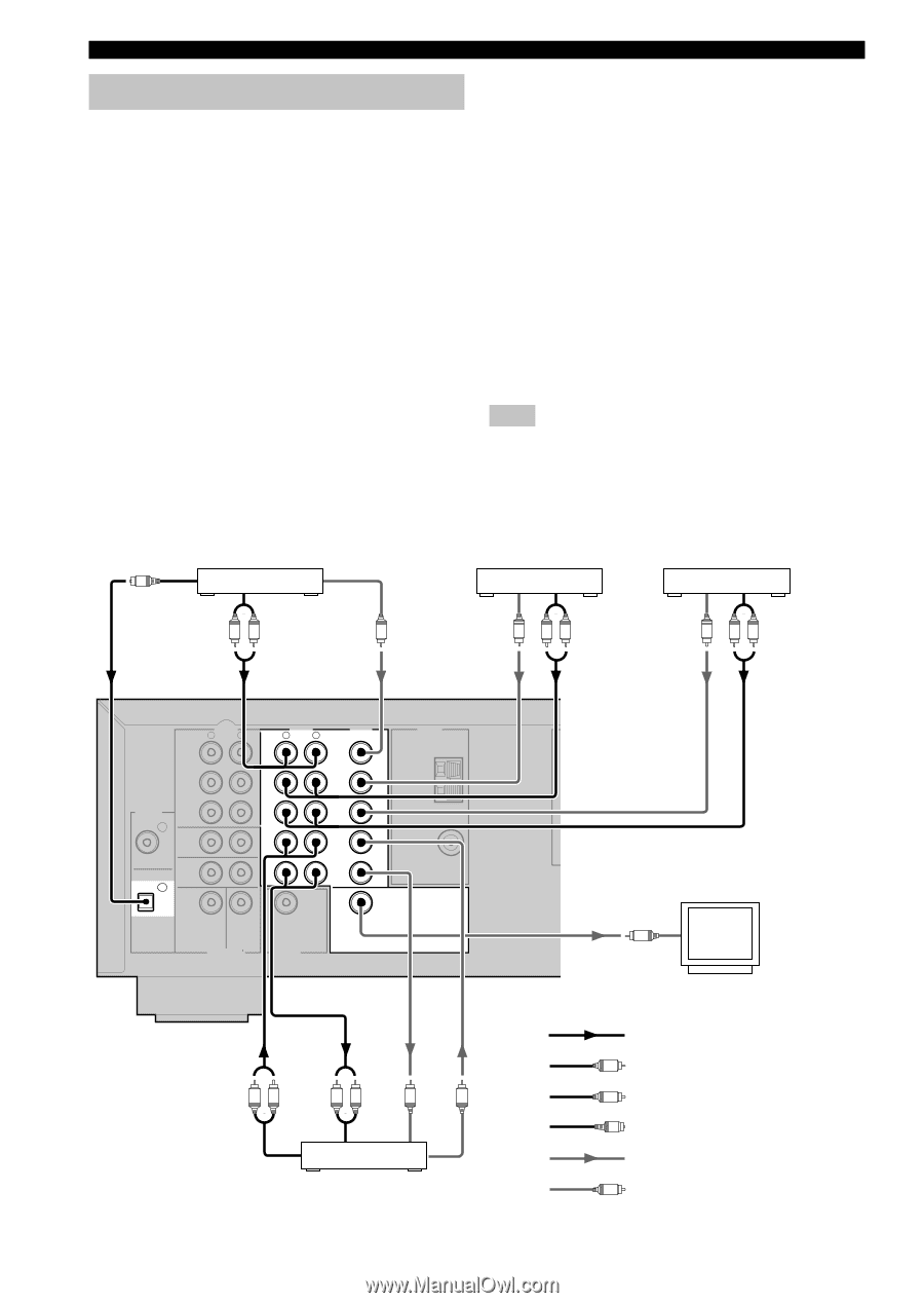
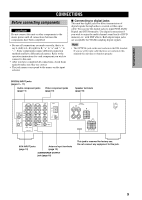
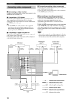
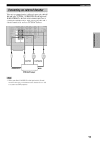
CONNECTIONS Connecting video components I Connecting a video monitor Connect the video input jack on your video monitor to the MONITOR OUT VIDEO jack. I Connecting a DVD player Connect the optical digital audio signal output jack on your component to the DIGITAL INPUT jack and connect the video signal output jack on the component to the VIDEO jack on this unit. y • Use the AUDIO jacks on this unit for a video component which does not have optical digital output jack. However, multi-channel reproduction cannot be obtained with audio signals input from the AUDIO jacks. I Connecting a digital TV/cable TV Connect the video signal output jack on your component to the VIDEO jack on this unit. Connect the audio signal output jacks on the component to the AUDIO jacks on this unit. I Connecting another video component Connect the video signal output jack on your component to the VIDEO jack on this unit. Connect the audio signal output jacks on the component to the AUDIO jacks on this unit. I Connecting a recording component Connect the audio signal input jacks on your video component to the AUDIO OUT jacks on this unit. Then connect the video signal input jack on the video component to the VIDEO OUT jack on this unit for picture recording. Connect the audio signal output jacks on your component to the AUDIO IN jacks on this unit. Then connect the video signal output jack on the component to the VIDEO IN jack on this unit to play a source from your recording component. Note • Once you have connected a recording component to this unit, keep its power turned on while using this unit. If the power is off, this unit may distort the sound from other components. O OPTICAL OUTPUT DVD player AUDIO L R OUTPUT TV/digital TV/ cable TV Another video component VIDEO VIDEO AUDIO VIDEO AUDIO V OUTPUT OUTPUT V L R OUTPUT OUTPUT V L R OUTPUT AUDIO R L CD DIGITAL INPUT CD 2 IN (PLAY) MD /CD-R OUT (REC) MAIN COAXIAL OPTICAL DVD 1 SURROUND SUB WOOFER CENTER AUDIO R L VIDEO DVD D-TV /CBL V-AUX IN VCR OUT TUNER AM ANT GND 75Ω UNBAL. FM ANT SUB WOOFER MONITOR OUT 6CH INPUT OUTPUT AUDIO AUDIO OUTPUT L R INPUT L R VIDEO VIDEO V INPUT V OUTPUT VCR 10 V VIDEO INPUT Video monitor indicates audio signal direction L indicates left analog cables R indicates right analog cables O indicates optical cables indicates video signal direction V indicates video cables
-
 1
1 -
2
-
3
-
4
-
5
-
6
-
7
-
8
-
 9
9 -
 10
10 -
 11
11 -
 12
12 -
 13
13 -
 14
14 -
 15
15 -
 16
16 -
 17
17 -
 18
18 -
 19
19 -
20
-
21
-
22
-
23
-
24
-
25
-
26
-
27
-
28
-
29
-
30
-
31
-
32
-
33
-
34
-
35
-
36
-
37
-
38
-
39
-
40
-
41
-
42
-
43
-
44
-
45
-
46
-
47
-
48
-
49
-
50
-
51
-
52
-
53
-
54
-
55
-
56
-
57
-
58
-
59
-
60
 |
 |