Yamaha HTR-5660 Owners Manual - Page 13
PREPARATION, CONNECTIONS, Before connecting components - subwoofer
 |
View all Yamaha HTR-5660 manuals
Add to My Manuals
Save this manual to your list of manuals |
Page 13 highlights
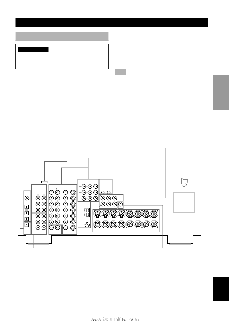
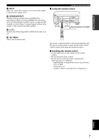
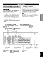
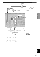
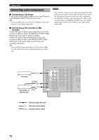
PREPARATION CONNECTIONS Before connecting components CAUTION Do not connect this unit or other components to the mains power until all connections between the components have been completed. • Be sure all connections are made correctly, that is to say L (left) to L, R (right) to R, "+" to "+" and "-" to "-". Some components require different connection methods and have different jack names. Refer to the operation instructions for each component you wish to connect to this unit. • After you have completed all connections, check them again to make sure they are correct. • The jack names correspond to the names on the input selector. I Connecting to digital jacks This unit has digital jacks for direct transmission of digital signals through either coaxial or fiber optic cables. You can use the digital jacks to input PCM, Dolby Digital and DTS bitstreams. Use digital connections if you wish to enjoy the multi-channel sound track of DVD material, etc. with DSP effects. All digital input jacks are acceptable for 96 kHz sampling digital signals. Note • The OPTICAL jacks on this unit conform to the EIA standard. If you use a fiber optic cable that does not conform to this standard this unit may not function properly. This jack is reserved for factory use. Do not connect any equipment to this jack. REMOTE CONTROL jacks (page 49) (U.S.A., Canada and Australia models only) DIGITAL INPUT jacks (pages 9 - 12) OUTPUT jacks (page 14) Audio component jacks (page 12) Video component jacks (pages 10 - 11) AUDIO DIGITAL INPUT CD 5 R L CD COAXIAL 4 OPTICAL D-TV/CBL DVD 3 IN (PLAY) MD /CD-R OUT (REC) 2 MD/CD-R MAIN SURROUND 1 MD/CD-R OPTICAL DIGITAL OUTPUT SUB WOOFER CENTER 6CH INPUT AUDIO R L VIDEO VIDEO S VIDEO DVD COMPORNENT VIDEO PR PB Y DVD A D-TV /CBL B D-TV /CBL MONITOR OUT IN VCR-1 OUT IN VCR 2 /DVR OUT TUNER AM ANT GND 75Ω UNBAL. FM ANT ZONE 2 OUT VIDEO S VIDEO MONITOR OUT REMOTE CONTROL IN OUT OUTPUT L CENTER R MAIN REAR (SURROUND) REAR CENTER SUB WOOFER SPEAKERS A R REAR L (SURROUND) B R MAIN L CENTER REAR CENTER 6CH INPUT jacks (page 14) Antenna input terminals (page 13) SUBWOOFER OUTPUT AC OUTLETS jack (page 17) (page 18) DIGITAL OUTPUT jack (page 12) ZONE 2 OUT jacks (page 49) (U.S.A., Canada and Australia models only) Speaker terminals (page 17) English 9
-
 1
1 -
2
-
3
-
4
-
5
-
6
-
7
-
 8
8 -
 9
9 -
 10
10 -
 11
11 -
 12
12 -
 13
13 -
 14
14 -
 15
15 -
 16
16 -
 17
17 -
 18
18 -
19
-
20
-
21
-
22
-
23
-
24
-
25
-
26
-
27
-
28
-
29
-
30
-
31
-
32
-
33
-
34
-
35
-
36
-
37
-
38
-
39
-
40
-
41
-
42
-
43
-
44
-
45
-
46
-
47
-
48
-
49
-
50
-
51
-
52
-
53
-
54
-
55
-
56
-
57
-
58
-
59
-
60
-
61
-
62
-
63
-
64
-
65
-
66
-
67
-
68
 |
 |