Yamaha IM8-24 Owner's Manual - Page 8
Controls and Functions, Channel Control - console
 |
View all Yamaha IM8-24 manuals
Add to My Manuals
Save this manual to your list of manuals |
Page 8 highlights
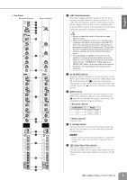
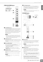
English Controls and Functions Controls and Functions Channel Control Section • Rear Panel Monaural channels Stereo channels NOTE · Patching external devices via an INSERT jack requires a special insert cable such as illustrated below (insert cable sold separately). To the input jack of the external processor To the INSERT jack Tip: OUT 1 4 2 3 Turn off the Yamaha PW8 power supply before you connect or disconnect any cables to or from the console. 1 INPUT Jack (monaural) These monaural input jacks are used to connect microphones or musical instruments. Each input channel features two types of jacks (INPUT A and INPUT B). • INPUT A Jack These are balanced XLR-3-31 type input jacks (1: Ground; 2: Hot; 3: Cold). • INPUT B Jack These are TRS phone-jack type balanced inputs. (T: Hot; R; Cold; S: Ground) You can connect either balanced or unbalanced phone plugs to these jacks. NOTE · Only one type of jack can be used at a time on a single channel. 2 INSERT Jack These jacks are located between the compressor and equalizer of the corresponding monaural input channel. The INSERT jacks are ideal for connecting devices such as graphic equalizers or noise filters into the corresponding channels. The INSERT jacks are TRS (tip, ring, sleeve) phone jacks that carry both the send and return signal (tip = send/out; ring = return/in; sleeve = ground). Sleeve (Ground) Ring: IN Tip: OUT Tip: IN To the output jack of the external processor 3 DIRECT OUT Jack These are impedance balanced (page 19) phone-jack type outputs. They output the signal that has passed through the compressor. NOTE · If necessary, the signal that is output from the DIRECT OUT jack can be changed to the signal immediately before the channel fader (pre-fader) or the signal after the channel fader (post-fader) by changing an internal jumper. A fee will be charged for this modification. For details, contact to your Yamaha dealer listed at the end of this manual. 4 INPUT Jacks (stereo) These are stereo input jacks that connect line-level instruments, such as a synthesizer. Each input channel features two types of jacks (INPUT A and INPUT B). • INPUT A Jacks These are unbalanced phone-jack stereo line inputs. • INPUT B Jacks These are unbalanced stereo RCA pin-jack line inputs. NOTE · Only one type of jack can be used at a time on a single channel. 8 Owner's Manual
-
 1
1 -
2
-
 3
3 -
 4
4 -
 5
5 -
 6
6 -
 7
7 -
 8
8 -
 9
9 -
 10
10 -
 11
11 -
 12
12 -
 13
13 -
14
-
15
-
16
-
17
-
18
-
19
-
20
-
21
-
22
-
23
-
24
-
25
-
26
-
27
-
28
-
29
-
30
-
31
-
32
-
33
-
34
 |
 |
