Yamaha LS9-32 Ls9 Editor Owner's Manual - Page 13
Overview window, INPUT CH window - phantom power
 |
View all Yamaha LS9-32 manuals
Add to My Manuals
Save this manual to your list of manuals |
Page 13 highlights
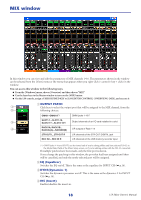
Overview window INPUT CH window This window displays the mix parameters of INPUT CH 1-16, 17-32, 33-48(*), or 49-64(*). The parameters shown in the window can be selected from the [View] menu or the menu that appears when you right-click ( key + click) in the window. You can access this window in the following ways. ● From the [Windows] menu, choose [Overview] and select CH1-16/CH17-32/33-48(*)/49-64(*) ● Use the layer keys in the Master window to turn on the [1-16] button / [17-32] button / [33-48] button(*)/ [49-64] button(*) ● On the LS9 itself, assign one of the USER DEFINED KEYS to [CH1-16]/[CH17-32]/[CH33-48](*)/[CH49-64](*) in [OVERVIEW] of [LS9 EDITOR CONTROL], and execute the function (*) INPUT CH 33-48, 49-64 can be viewed only if LS9-32 is selected in the Model Select field of the Mixer Setup window when editing offline, or when editing online with the LS9-32. 1 A Input patch Click here to select the input source that will be assigned to the INPUT CH, from the 2 following choices. 3 NONE IN 1-IN32(*) No assignment INPUT jacks 1-32(*) SLOT1-1...SLOT1-16, SLOT2-1(*)...SLOT2-16(*) Input channels of an I/O card installed in a slot 2TR IN L, 2TR IN R L/R channels of the 2TR DIN jack PB OUT L, PB OUT R L/R channels of USB memory recorder output RACK1A, RACK1B... RACK5L(A)...RACK8R(B) L/R outputs of Rack 1-8 (*) INPUT jacks 17-32 and slot 2 can be viewed only if you're editing offline and have selected LS9-32 in the Model Select field of the Mixer Setup screen, or if you're editing online with the LS9-32. B HA GAIN Drag the knob in the screen to adjust the gain of the internal head amp or of the external head amp (AD8HR) patched to the INPUT CH. C 48V Switches on/off the phantom power (+48V) of the internal head amp or of the external head amp (AD8HR) patched to the INPUT CH. 13 LS9 Editor Owner's Manual
-
 1
1 -
2
-
3
-
4
-
5
-
6
-
7
-
 8
8 -
 9
9 -
 10
10 -
 11
11 -
 12
12 -
 13
13 -
 14
14 -
 15
15 -
 16
16 -
 17
17 -
 18
18 -
19
-
20
-
21
-
22
-
23
-
24
-
25
-
26
-
27
-
28
-
29
-
30
-
31
-
32
-
33
-
34
-
35
-
36
-
37
-
38
-
39
-
40
-
41
-
42
-
43
-
44
-
45
-
46
-
47
-
48
-
49
-
50
-
51
-
52
-
53
-
54
-
55
-
56
-
57
-
58
-
59
-
60
-
61
-
62
-
63
-
64
-
65
-
66
-
67
-
68
-
69
-
70
-
71
-
72
-
73
-
74
-
75
-
76
-
77
-
78
-
79
-
80
 |
 |
