Yamaha LS9-32 Ls9 Editor Owner's Manual - Page 18
MIX window, AOUTPUT PATCH BEQ Equalizer CDYN1Dynamics 1 DINS Insert - x 16 digital console
 |
View all Yamaha LS9-32 manuals
Add to My Manuals
Save this manual to your list of manuals |
Page 18 highlights
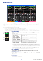
MIX window In this window you can view and edit the parameters of MIX channels 1-16. The parameters shown in the window can be selected from the [View] menu or the menu that appears when you right-click ( key + click) in the window. You can access this window in the following ways. ● From the [Windows] menu, choose [Overview] and then choose "MIX" ● Use the layer keys in the Master window to turn on the [MIX] button ● On the LS9 console, assign a USER DEFINED KEY to [LS9 EDITOR CONTROL]-[OVERVIEW]-[MIX], and execute it A OUTPUT PATCH 1 Click here to select the output port that will be assigned to the MIX channel, from the 2 following choices. OMNI1-OMNI16(*) OMNI jacks 1-16(*) 3 SLOT1-1...SLOT1-16, SLOT2-1(*)...SLOT2-16(*) Output channels of an I/O card installed in a slot 4 RACK1A, RACK1B... RACK5L(A)...RACK8R(B) L/R outputs of Rack 1-8 2TR OUT L, 2TR OUT R L/R channels of the 2TR OUT DIGITAL jack REC IN L, REC IN R L/R channels of the USB memory recorder input (*) OMNI jacks 9-16 and SLOT2 can be viewed only if you're editing offline and have selected LS9-32 in the Model Select field of the Mixer Setup screen, or if you're editing online with the LS9-32 connected. If multiple patches have been made, only the first port is shown. If you change the patching in this window, the port that had been assigned until then will be cancelled, and only the newly selected port will be assigned. B EQ (Equalizer) Switches the EQ on/off. This is the same as the equalizer for INPUT CH (➥ p.14). C DYN1(Dynamics 1) Switches the dynamics processor on/off. This is the same as the dynamics 2 for INPUT CH (➥ p.14). D INS (Insert) Enables/disables the insert-in. 18 LS9 Editor Owner's Manual
-
 1
1 -
2
-
3
-
4
-
5
-
6
-
7
-
8
-
9
-
10
-
11
-
12
-
 13
13 -
 14
14 -
 15
15 -
 16
16 -
 17
17 -
 18
18 -
 19
19 -
 20
20 -
 21
21 -
 22
22 -
 23
23 -
24
-
25
-
26
-
27
-
28
-
29
-
30
-
31
-
32
-
33
-
34
-
35
-
36
-
37
-
38
-
39
-
40
-
41
-
42
-
43
-
44
-
45
-
46
-
47
-
48
-
49
-
50
-
51
-
52
-
53
-
54
-
55
-
56
-
57
-
58
-
59
-
60
-
61
-
62
-
63
-
64
-
65
-
66
-
67
-
68
-
69
-
70
-
71
-
72
-
73
-
74
-
75
-
76
-
77
-
78
-
79
-
80
 |
 |
