Yamaha MOX8 Reference Manual - Page 8
Memory structure of Mixing, A/D Input Block - midi setup
 |
UPC - 086792950907
View all Yamaha MOX8 manuals
Add to My Manuals
Save this manual to your list of manuals |
Page 8 highlights
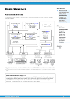
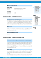
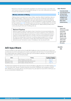
Mixing Part. In this case, the sound of the Song/Pattern you created may change unexpectedly if you edit or delete the Voice used for the Song/Pattern Mixing in the Voice mode. Mixing Voices are provided to prevent these accidental sound changes. Memory structure of Mixing A Mixing program is provided for each Song or Pattern. Selecting a different Song/Pattern calls up a different Mixing program. A Mixing Voice provides 16 memories for each Mixing program (Song or Pattern). Selecting a different Song/Pattern calls up the different Mixing Voice as well as the Mixing program. If you wish to use a Mixing Voice of a certain Song/Pattern for another Song/Pattern, execute the Copy operation (page 123) in the Mixing Voice Job. Note that up to 256 Mixing Voices can be stored for all Songs and Patterns. If the memory for Mixing Voices is full, delete the Mixing Voices you don't need by executing the Delete job of the Mixing Voice job. Maximum Polyphony Maximum polyphony refers to the highest number of notes that can be sounded simultaneously from the internal tone generator of the instrument. The maximum polyphony of this synthesizer is 64. When the internal tone generator block receives a number of notes exceeding the maximum polyphony, previously played notes are cut off. Keep in mind this may be especially noticeable with Voices not having decay. Furthermore, the maximum polyphony applies to the number of Voice Elements used, not the number of Voices. When Normal Voices that include up to eight Elements are used, the maximum number of simultaneous notes may be less than 64. Basic Structure Functional blocks Tone Generator block A/D Input block Sequencer block Arpeggio block Controller block Effect block Internal memory Reference Voice mode Performance mode Song mode Pattern mode Mixing mode Master mode Remote mode Utility mode Quick setup File mode A/D Input Block This block handles the audio signal input from the A/D INPUT [L]/[R] jacks. Various parameters such as volume, pan, and effect can be set for the audio signal and the sound is output together with other Voices. The Insertion Effect as well as the System Effects can be applied to the audio signal input via the A/D INPUT [L]/[R] jacks. The A/D Input block related parameters can be set in the following display. Appendix MIDI Mode Voice mode Performance mode Song/Pattern mode Display VCE A/D display in the Utility mode A/D IN display in Performance Common Edit A/D IN display in Mixing Common Edit Corresponding page in the Reference Manual Page 145 Page 62 Page 116 The effect which is applied to the audio signal input from the A/D INPUT [L]/[R] jacks is set in the USB I/O display (page 147) of the Utility mode. The gain of the audio signal from the A/D INPUT [L]/[R] jacks can be adjusted via the A/D INPUT [GAIN] knob on the panel. Moreover, the on/off setting of the audio signal from the A/D INPUT [L]/[R] jacks can be set via the A/D INPUT [ON/OFF] button. MOX6/MOX8 Reference Manual 8
-
 1
1 -
2
-
 3
3 -
 4
4 -
 5
5 -
 6
6 -
 7
7 -
 8
8 -
 9
9 -
 10
10 -
 11
11 -
 12
12 -
 13
13 -
14
-
15
-
16
-
17
-
18
-
19
-
20
-
21
-
22
-
23
-
24
-
25
-
26
-
27
-
28
-
29
-
30
-
31
-
32
-
33
-
34
-
35
-
36
-
37
-
38
-
39
-
40
-
41
-
42
-
43
-
44
-
45
-
46
-
47
-
48
-
49
-
50
-
51
-
52
-
53
-
54
-
55
-
56
-
57
-
58
-
59
-
60
-
61
-
62
-
63
-
64
-
65
-
66
-
67
-
68
-
69
-
70
-
71
-
72
-
73
-
74
-
75
-
76
-
77
-
78
-
79
-
80
-
81
-
82
-
83
-
84
-
85
-
86
-
87
-
88
-
89
-
90
-
91
-
92
-
93
-
94
-
95
-
96
-
97
-
98
-
99
-
100
-
101
-
102
-
103
-
104
-
105
-
106
-
107
-
108
-
109
-
110
-
111
-
112
-
113
-
114
-
115
-
116
-
117
-
118
-
119
-
120
-
121
-
122
-
123
-
124
-
125
-
126
-
127
-
128
-
129
-
130
-
131
-
132
-
133
-
134
-
135
-
136
-
137
-
138
-
139
-
140
-
141
-
142
-
143
-
144
-
145
-
146
-
147
-
148
-
149
-
150
-
151
-
152
-
153
-
154
-
155
-
156
-
157
-
158
-
159
-
160
 |
 |
