Yamaha PF-500 Owner's Manual - Page 19
Panel Logos, Exit] Button, Aux In, Aux Out, Phones], Power On/off], Ac Inlet], Pedal], P14, 101, Aux
 |
View all Yamaha PF-500 manuals
Add to My Manuals
Save this manual to your list of manuals |
Page 19 highlights
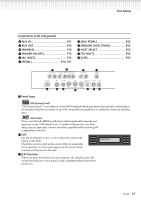
Part Names Connectors (Left side panel) R AUX IN P51 S AUX OUT P52 T [PHONES P16 U [POWER ON/OFF P15 V [AC INLET P15 W [PEDAL P14, 101 X [AUX PEDAL P52 Y MIDI [IN] [OUT] [THRU P52 Z HOST SELECT P52 [ [TO HOST P52 \ [USB P52 R AUX IN L/L+R R L/L+R S AUX OUT R L LEVEL FIXED R T PHONES U POWER ON OFF AC INLET V PEDAL AUX PEDAL IN WX MIDI HOST SELECT TO HOST MIDI PC-2 Mac USB USB OUT Y THRU Z [\ ] Panel logos GM System Level 1 "GM System Level 1" is an addition to the MIDI standard which guarantees that any data conforming to the standard will play accurately on any GM-compatible tone generator or synthesizer from any manufacturer. XG Format XG is a new Yamaha MIDI specification which significantly expands and improves on the "GM System Level 1" standard with greater voice handling capacity, expressive control, and effect capability while retaining full compatibility with GM. C LCD A B Use the LCD button A, B, C, or D to select the contents disNO YES played on the LCD. Check the screen located in the center of the top panel after C D every operation. A voice name appears on the screen when you turn on the power to the unit. E [EXIT] button When you press this button, the unit returns to the default screen (the screen that indicates a voice name(s) and is displayed when the power is turned on). PF-500 19
-
 1
1 -
2
-
3
-
4
-
5
-
6
-
7
-
8
-
9
-
10
-
11
-
12
-
13
-
 14
14 -
 15
15 -
 16
16 -
 17
17 -
 18
18 -
 19
19 -
 20
20 -
 21
21 -
 22
22 -
 23
23 -
 24
24 -
25
-
26
-
27
-
28
-
29
-
30
-
31
-
32
-
33
-
34
-
35
-
36
-
37
-
38
-
39
-
40
-
41
-
42
-
43
-
44
-
45
-
46
-
47
-
48
-
49
-
50
-
51
-
52
-
53
-
54
-
55
-
56
-
57
-
58
-
59
-
60
-
61
-
62
-
63
-
64
-
65
-
66
-
67
-
68
-
69
-
70
-
71
-
72
-
73
-
74
-
75
-
76
-
77
-
78
-
79
-
80
-
81
-
82
-
83
-
84
-
85
-
86
-
87
-
88
-
89
-
90
-
91
-
92
-
93
-
94
-
95
-
96
-
97
-
98
-
99
-
100
-
101
-
102
-
103
-
104
-
105
-
106
-
107
-
108
 |
 |
