Yamaha RX-V2095 Owner's Manual - Page 29
Antennas
 |
View all Yamaha RX-V2095 manuals
Add to My Manuals
Save this manual to your list of manuals |
Page 29 highlights
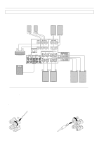
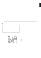
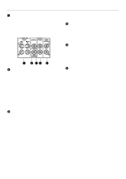
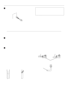
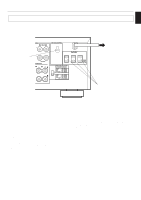
English PREPARATION Antennas q Each antenna should be connected to the designated terminals correctly, as shown in the following figure. q Both AM and FM indoor antennas are included with this unit. In general, these antennas will probably provide sufficient signal strength. Nevertheless, a properly installed outdoor antenna will give clearer reception than an indoor one. If you experience poor reception quality only with the indoor antennas, the use of an outdoor antenna may result in improvement. Outdoor AM antenna Outdoor FM antenna Indoor FM antenna (included) (U.S.A. model) AM loop antenna (included) 75-ohm/300-ohm antenna adapter 75-ohm coaxial cable 75-ohm/300-ohm antenna adapter 300-ohm flat ribbon cable AM ANT GND FM ANT 75Ω UNBAL. GND COAXIAL AUDIO SIGNAL PHONO 1 CD 3 IN ( PLAY ) TAPE/MD 4 OUT ( REC ) MAIN SURROUND EXTERNAL DECODER INPUT SUB WOOFER CENTER CD DVD/LD CD IN OUT (PLAY) TAPE/MD (REC) DIGITAL SIGNAL Ground Ⅵ Connecting the AM loop antenna 1. Press the tab and unlock the terminal hole. 2. Connect the AM loop antenna lead wires to the AM ANT and GND terminals. 3. Return the tab back to the original position to lock the lead wires. Lightly pull on the lead wires to confirm a good connection. 1 3 2 4. Attach the loop antenna to the antenna stand. Loop antenna Antenna stand 5. Orient the AM loop antenna so that the best reception is obtained. Notes q The AM loop antenna should be placed apart from the main unit. The antenna may be hung on a wall. q The AM loop antenna should be kept connected, even if an outdoor AM antenna is connected to this unit. 25
-
 1
1 -
2
-
3
-
4
-
5
-
6
-
7
-
8
-
9
-
10
-
11
-
12
-
13
-
14
-
15
-
16
-
17
-
18
-
19
-
20
-
21
-
22
-
23
-
 24
24 -
 25
25 -
 26
26 -
 27
27 -
 28
28 -
 29
29 -
 30
30 -
 31
31 -
 32
32 -
 33
33 -
 34
34 -
35
-
36
-
37
-
38
-
39
-
40
-
41
-
42
-
43
-
44
-
45
-
46
-
47
-
48
-
49
-
50
-
51
-
52
-
53
-
54
-
55
-
56
-
57
-
58
-
59
-
60
-
61
-
62
-
63
-
64
-
65
-
66
-
67
-
68
-
69
-
70
-
71
-
72
-
73
-
74
-
75
-
76
-
77
-
78
-
79
-
80
-
81
-
82
-
83
-
84
-
85
-
86
-
87
-
88
-
89
-
90
 |
 |
