Yamaha YSP-1 Owner's Manual - Page 13
Bottom panel, SUBWOOFER OUT jack
 |
UPC - 027108921426
View all Yamaha YSP-1 manuals
Add to My Manuals
Save this manual to your list of manuals |
Page 13 highlights
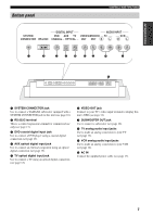
INTRODUCTION Bottom panel CONTROLS AND FUNCTIONS DIGITAL INPUT SYSTEM DVD AUX TV CONNECTOR RS-232C COAXIAL OPTICAL AUDIO INPUT VIDEOSUBWOOFER TV OUT OUT R L VCR R L 1 2 3 4 5 67 8 9 0 1 SYSTEM CONNECTOR jack Use to connect a YAMAHA subwoofer equipped with a SYSTEM CONNECTOR jack to this unit (see page 16). 2 RS-232C terminal This is a control expansion terminal for commercial use only (see page 17). 3 DVD coaxial digital input jack Use to connect a DVD player using a coaxial digital connection (see page 13). 4 AUX optical digital input jack Use to connect an external component using an optical digital connection (see page 15). 5 TV optical digital input jack Use to connect a TV using an optical digital connection (see page 12). 6 VIDEO OUT jack Connect to your TV's video input terminal to display this unit's OSD (see page 12). 7 SUBWOOFER OUT jack Use to connect a subwoofer (see page 16). 8 TV analog audio input jacks Use to make an analog connection to your TV (see page 12). 9 VCR analog audio input jacks Use to make an analog connection to your VCR (see page 14). 0 AC IN Connect the supplied power cable (see page 17). 7
-
 1
1 -
2
-
3
-
4
-
5
-
6
-
7
-
 8
8 -
 9
9 -
 10
10 -
 11
11 -
 12
12 -
 13
13 -
 14
14 -
 15
15 -
 16
16 -
 17
17 -
 18
18 -
19
-
20
-
21
-
22
-
23
-
24
-
25
-
26
-
27
-
28
-
29
-
30
-
31
-
32
-
33
-
34
-
35
-
36
-
37
-
38
-
39
-
40
-
41
-
42
-
43
-
44
-
45
-
46
-
47
-
48
-
49
-
50
-
51
-
52
-
53
-
54
-
55
-
56
-
57
-
58
-
59
-
60
-
61
-
62
-
63
-
64
-
65
-
66
-
67
-
68
-
69
-
70
 |
 |
