Zanussi ZCG55QGX Product Manaul - Page 21
P.T.F.E. sealant tape.
 |
View all Zanussi ZCG55QGX manuals
Add to My Manuals
Save this manual to your list of manuals |
Page 21 highlights
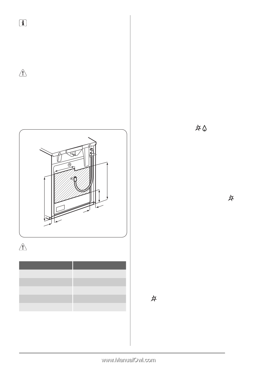
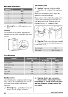
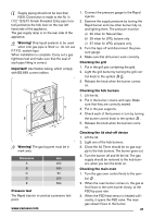
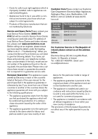
Supply piping should not be less than R3/8. Connection is made to the Rc ½ (1/2 " B.S.P.) female threaded. Entry pipe located just below the hob level on the rear left hand side of the appliance. The gas supply ramp is on the rear side of the appliance. Warning! Only liquid sealants to be used when inlet gas pipe is fitted i.e.: do not use P.T.F.E. sealant tape. When installation is complete. Carry out a gas tightness test and make sure that the seal of each pipe fitting is correct. Important! Use flexible tubing, which comply with BS.669 current edition. A B C E D C Warning! The gas bayonet must be in mark area. Dimension mm A 250 B 680 C 50 D 250 E 580 Pressure test The Rapid injector is used as a pressure test point. www.zanussi.com 1. Connect the pressure gauge to the Rapid injector. 2. Examine the supply pressure by turning the Rapid burner and one other burner fully on, and lighting them. The pressure must be: a) 20 mbar for Natural Gas b) 29 mbar for LPG, butane only c) 37 mbar for LPG, propane only. 3. Turn the taps off and disconnect the pressure gauge. 4. Make sure that all burners work correctly. Checking the grill 1. Put in the grill pan containing the grid. 2. Light the grill burner by turning the grill con- trol knob to the symbol . 3. Release the knob when the burner comes on. Checking the hob burners 1. Lift the lid. 2. Put in the burner crowns and caps. Make sure that they are correctly seated. 3. Put in the pan supports. 4. Check each of the burners in turn by turning the burner control knob to the symbol . 5. Release the knob when the burners come on. Checking the lid shut-off device 1. Lift the lid. 2. Light one of the hob burners. 3. Close the lid. There should be no gas sup- ply to the hob burners. The burner goes out. 4. Turn the burner off and lift the lid. The gas supply should be restored to the hob burners, when you turn the knob on. Checking the main oven 1. Turn the gas oven control knob to the sym- bol . 2. When the oven burner comes on, the gas at first flows to the oven burner slowly, at the FSD by-pass rate. 3. When the FSD heat sensor is heated sufficiently, it opens the FSD valve. The main gas stream flows to the burner. 21
-
 1
1 -
2
-
3
-
4
-
5
-
6
-
7
-
8
-
9
-
10
-
11
-
12
-
13
-
14
-
15
-
 16
16 -
 17
17 -
 18
18 -
 19
19 -
 20
20 -
 21
21 -
 22
22 -
 23
23 -
 24
24 -
 25
25 -
 26
26 -
27
-
28
 |
 |