Zenith XBV613 Service Manual - Page 13
Vcr Part - remote
 |
UPC - 719192169715
View all Zenith XBV613 manuals
Add to My Manuals
Save this manual to your list of manuals |
Page 13 highlights
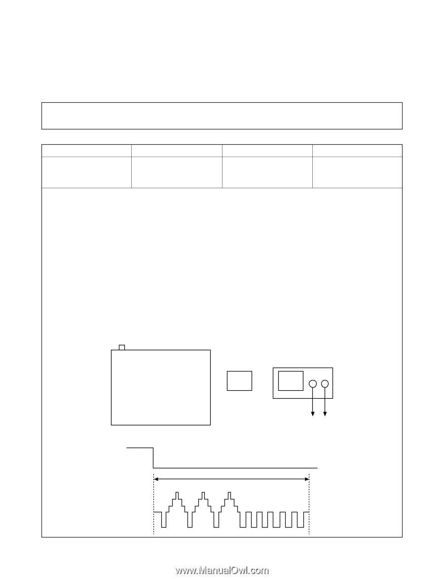
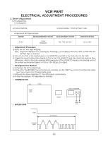
VCR PART ELECTRICAL ADJUSTMENT PROCEDURES 1. Servo Adjustment 1) PG Adjustment • Test Equipment a) OSCILLOSCOPE b) NTSC MODEL : NTSC SP TEST TAPE • Adjustment And Specification MODE MEASUREMENT POINT ADJUSTMENT POINT SPECIFICATION PLAY V.Out H/SW(TP) R/C TRK JIG KEY 6.5 ± 0.5H • Adjustment Procedure a) Insert the SP Test Tape and play. Note - Adjust the distance of X, pressing the Tracking(+) or Tracking(-) when the "ATR" is blink after the SP Test Tape is inserted. b) Connect the CH1 of the oscilloscope to the H/SW(TP) and CH2 to the Video Out for the VCR. c) Trigger the mixed Combo Video Signal of CH2 to the CH1 H/SW(TP) and then check the distance (time difference), which is from the selected A(B) Head point of the H/SW(TP) signal to the starting point of the vertical synchronized signal, to 6.5H ± 0.5H (412µs, 1H=63µs). • PG Adjustment Method a-1) Payback the SP standard tape b-2) Press the "OK(ENTER)" key on the Remote controller and the "REC" key on the Front Panel the same time, then it goes in to Tracking initial mode. c-3) Repeat the above step(No.b-2), then PG adjusts automatically. d-4) Stop the playback, PG adjustment is finished. • CONNECTION V.Out H/SW (TP) OSCILLOSCOPE CH1 CH2 R/C KEY • WAVEFORM H/SW V.out (TP) H/SW Composite VIDEO 6.5H(412µs) 3-2
-
 1
1 -
2
-
3
-
4
-
5
-
6
-
7
-
 8
8 -
 9
9 -
 10
10 -
 11
11 -
 12
12 -
 13
13 -
 14
14 -
 15
15 -
 16
16 -
 17
17 -
 18
18 -
19
-
20
-
21
-
22
-
23
-
24
-
25
-
26
-
27
-
28
-
29
-
30
-
31
-
32
-
33
-
34
-
35
-
36
-
37
-
38
-
39
-
40
-
41
-
42
-
43
-
44
-
45
-
46
-
47
-
48
-
49
-
50
-
51
-
52
-
53
-
54
-
55
-
56
-
57
-
58
-
59
-
60
-
61
-
62
-
63
-
64
-
65
-
66
-
67
-
68
-
69
-
70
-
71
-
72
-
73
-
74
-
75
-
76
-
77
-
78
-
79
-
80
-
81
-
82
-
83
-
84
-
85
-
86
-
87
-
88
-
89
-
90
-
91
-
92
-
93
-
94
-
95
-
96
-
97
-
98
-
99
-
100
-
101
-
102
-
103
-
104
-
105
-
106
-
107
-
108
-
109
-
110
-
111
-
112
-
113
-
114
-
115
-
116
-
117
-
118
-
119
-
120
-
121
-
122
-
123
-
124
-
125
-
126
-
127
-
128
 |
 |