Zenith XBV613 Service Manual - Page 93
Guide Roller Height Adjustment
 |
UPC - 719192169715
View all Zenith XBV613 manuals
Add to My Manuals
Save this manual to your list of manuals |
Page 93 highlights
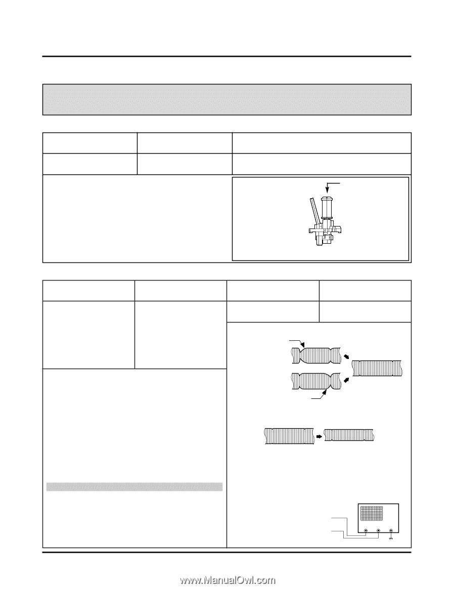
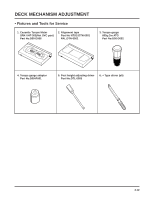
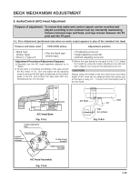
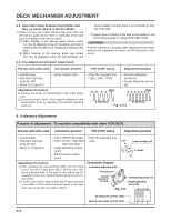
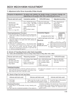
DECK MECHANISM ADJUSTMENT 4. Guide Roller Height Adjustment Purpose of adjustment : To ensure that the bottom surface of the tape can travel along with the tape lead line of the lower drum by constantly and adjusting and maintaining the height of the tape. 4-1. Prior Adjustment Fixtures and tools used VCR (VCP) status Adjustment position • Post Height Adjusting Driver • Play or Review Mode Adjustment Procedure 1) Travel the tape and check the bottom surface of the tape travels along with the guide line of the lower drum. 2) If the tape travels toward the lower part of guide line on the lower drum, turn the guide roller height adjusting screw to the left 3) If it travels to the upper part, turn it to the right. 4) Adjust the height of the guide roller to ensure that the tape is guided on the guide line of the lower drum at the inlet/outlet of the drum. (Fig. C-4-1) • The guide roller height adjusting screw on the supply guide roller and the take-up guide roller ADJUSTMENT DIAGRAM GUIDE ROLLER HEIGHT ADJUSTMENT SCREW Fig. C-4-1 4-2. Fine Adjustment Fixtures and tools used • Oscilloscope • Standard test tape • Post height adjusting driver Measuring tools and connection position VCR (VCP) status • CH-1: PB RF Envelope • Play the standard test • CH-2: NTSC : SW 30Hz tape. PAL : SW 25Hz • Head switching output point Waveform P2 POST ADJUSTMENT • RF Envelope output point Adjustment position • Guide roller height adjusting screw 1) Play the standard test tape after connecting the probe of oscilloscope to the RF envelope output point and the head switching output point. 2) Tracking control (playback) : Locate it at the center (Set the RF output to the maximum value via the tracking control when such adjustment is completed after the drum assembly is replaced.) 3) Height adjusting screw: Flatten the RF waveform. (Fig. C-4-2) 4) Move the tracking control (playback) to the right/left. (Fig. C-4-3) 5) Check the start and the end of the RF output reduction width are constant. P3 POST ADJUSTMENT Fig. C-4-2 Flatten the waveform by lightly turning the guide roller height adjustment screw. When the tracking control locates at the center. When turning the tracking control to both sides. Fig. C-4-2 CAUTIONS There must exist no crumpling and folding of the tape due to excess adjustment or insufficient adjustment. Connection Diagram RF ENVELOPE OUTPUT POINT HEAD RF SWITCHING OUTPUT POINT OSCILLOSCOPE CH-1 CH-2 4-15
-
 1
1 -
2
-
3
-
4
-
5
-
6
-
7
-
8
-
9
-
10
-
11
-
12
-
13
-
14
-
15
-
16
-
17
-
18
-
19
-
20
-
21
-
22
-
23
-
24
-
25
-
26
-
27
-
28
-
29
-
30
-
31
-
32
-
33
-
34
-
35
-
36
-
37
-
38
-
39
-
40
-
41
-
42
-
43
-
44
-
45
-
46
-
47
-
48
-
49
-
50
-
51
-
52
-
53
-
54
-
55
-
56
-
57
-
58
-
59
-
60
-
61
-
62
-
63
-
64
-
65
-
66
-
67
-
68
-
69
-
70
-
71
-
72
-
73
-
74
-
75
-
76
-
77
-
78
-
79
-
80
-
81
-
82
-
83
-
84
-
85
-
86
-
87
-
 88
88 -
 89
89 -
 90
90 -
 91
91 -
 92
92 -
 93
93 -
 94
94 -
 95
95 -
 96
96 -
 97
97 -
 98
98 -
99
-
100
-
101
-
102
-
103
-
104
-
105
-
106
-
107
-
108
-
109
-
110
-
111
-
112
-
113
-
114
-
115
-
116
-
117
-
118
-
119
-
120
-
121
-
122
-
123
-
124
-
125
-
126
-
127
-
128
 |
 |