Zenith XBV613 Service Manual - Page 89
Fig. A-9, Base Tension Fig. A-9-1
 |
UPC - 719192169715
View all Zenith XBV613 manuals
Add to My Manuals
Save this manual to your list of manuals |
Page 89 highlights
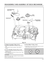
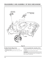
DISASSEMBLY AND ASSEMBLY OF DECK MECHANISM Base Tension (Fig. A-9-1) (A) Arm Assembly Idler Jog (Fig. A-9-2) (B) (C) Chassis (D) Fig. A-9 34. Base Tension (Fig. A-9-1) 1) Release the (A) part of the base tension from the embossing of chassis. 2) Hold the base tension upward while turning it anti-clockwise. 35. Arm assembly Idler Jog (Fig. A-9-2) 1) Push both (B), (C) parts in Fig. A-9-2 toward the arrow direction. 2) Disassemble the arm assembly idler upward. CAUTIONS Take care to ensure that the (D) part in the drawing is not hung to chassis in disassembly. 4-11
-
 1
1 -
2
-
3
-
4
-
5
-
6
-
7
-
8
-
9
-
10
-
11
-
12
-
13
-
14
-
15
-
16
-
17
-
18
-
19
-
20
-
21
-
22
-
23
-
24
-
25
-
26
-
27
-
28
-
29
-
30
-
31
-
32
-
33
-
34
-
35
-
36
-
37
-
38
-
39
-
40
-
41
-
42
-
43
-
44
-
45
-
46
-
47
-
48
-
49
-
50
-
51
-
52
-
53
-
54
-
55
-
56
-
57
-
58
-
59
-
60
-
61
-
62
-
63
-
64
-
65
-
66
-
67
-
68
-
69
-
70
-
71
-
72
-
73
-
74
-
75
-
76
-
77
-
78
-
79
-
80
-
81
-
82
-
83
-
 84
84 -
 85
85 -
 86
86 -
 87
87 -
 88
88 -
 89
89 -
 90
90 -
 91
91 -
 92
92 -
 93
93 -
 94
94 -
95
-
96
-
97
-
98
-
99
-
100
-
101
-
102
-
103
-
104
-
105
-
106
-
107
-
108
-
109
-
110
-
111
-
112
-
113
-
114
-
115
-
116
-
117
-
118
-
119
-
120
-
121
-
122
-
123
-
124
-
125
-
126
-
127
-
128
 |
 |

DISASSEMBLY AND ASSEMBLY OF DECK MECHANISM
4-11
(A)
(B)
(C)
Arm Assembly Idler Jog
Base Tension
Chassis
(D)
Fig. A-9
34. Base Tension (Fig. A-9-1)
1) Release the (A) part of the base tension from the
embossing of chassis.
2) Hold the base tension upward while turning it anti-clock-
wise.
35. Arm assembly Idler Jog (Fig. A-9-2)
1) Push both (B), (C) parts in Fig. A-9-2 toward the arrow
direction.
2) Disassemble the arm assembly idler upward.
CAUTIONS
Take care to ensure that the (D) part in the drawing is not
hung to chassis in disassembly.
(Fig. A-9-1)
(Fig. A-9-2)