Zenith XBV613 Service Manual - Page 91
Mechanism Assembly Mode Check
 |
UPC - 719192169715
View all Zenith XBV613 manuals
Add to My Manuals
Save this manual to your list of manuals |
Page 91 highlights
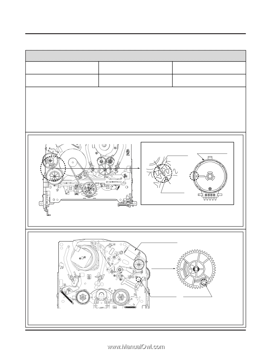
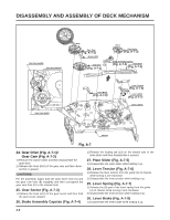
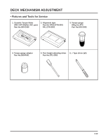
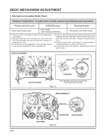
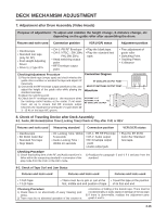
DECK MECHANISM ADJUSTMENT 1. Mechanism Assembly Mode Check Purpose of adjustment : To make tools normally operate by positioning tools accurately. Fixtures and tools used VCR (VCP) status Checking Position • Blank Tape (empty tape) • Eject Mode (with cassette withdrawn) • Mechanism and Mode Switch 1) Turn the VCR on and take the tape out by pressing the eject button. 2) Separate both top cover and plate top, and check both the hole (A) of gear cam and the hole (A') of chassis correspond (Fig. C-2). 3) If it is done as in the paragraph 2): Turn the gear cam as in No.2) after mantling the motor assembly L/D. 4) Undo the screw fixing the deck and the main frame, and separate the deck assembly. Check both the hole (A) of gear cam and the hole (A') of chassis correspond (Fig. C-1). 5) Check the mode S/W on the main P.C. board locates at a proper position as in (B) of the Fig. (C-1). 6) Connect the deck to the main P.C. board and perform all types of test. CHECK DIAGRAM Gear Cam Mode S/W BOTTOM VIEW (B) (C) Gear Drive Fig. C-1 Correspondence of the gear cam hole (O) and the gear drive hole (O) Motor Assembly L/D 4-13 Gear Cam (A') (A) Chassis Hole Gear Cam Hole TOP VIEW Fig. C-2
-
 1
1 -
2
-
3
-
4
-
5
-
6
-
7
-
8
-
9
-
10
-
11
-
12
-
13
-
14
-
15
-
16
-
17
-
18
-
19
-
20
-
21
-
22
-
23
-
24
-
25
-
26
-
27
-
28
-
29
-
30
-
31
-
32
-
33
-
34
-
35
-
36
-
37
-
38
-
39
-
40
-
41
-
42
-
43
-
44
-
45
-
46
-
47
-
48
-
49
-
50
-
51
-
52
-
53
-
54
-
55
-
56
-
57
-
58
-
59
-
60
-
61
-
62
-
63
-
64
-
65
-
66
-
67
-
68
-
69
-
70
-
71
-
72
-
73
-
74
-
75
-
76
-
77
-
78
-
79
-
80
-
81
-
82
-
83
-
84
-
85
-
 86
86 -
 87
87 -
 88
88 -
 89
89 -
 90
90 -
 91
91 -
 92
92 -
 93
93 -
 94
94 -
 95
95 -
 96
96 -
97
-
98
-
99
-
100
-
101
-
102
-
103
-
104
-
105
-
106
-
107
-
108
-
109
-
110
-
111
-
112
-
113
-
114
-
115
-
116
-
117
-
118
-
119
-
120
-
121
-
122
-
123
-
124
-
125
-
126
-
127
-
128
 |
 |