ZyXEL MES3500-24 User Guide - Page 194
Types of MVR Ports, MVR Modes, How MVR Works
 |
View all ZyXEL MES3500-24 manuals
Add to My Manuals
Save this manual to your list of manuals |
Page 194 highlights
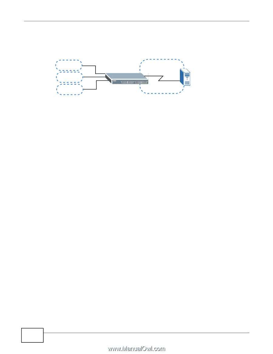
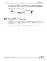
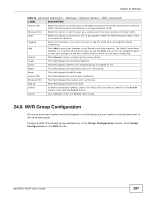
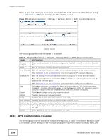
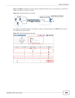
Chapter 24 Multicast The following figure shows a network example. The subscriber VLAN (1, 2 and 3) information is hidden from the streaming media server, S. In addition, the multicast VLAN information is only visible to the Switch and S. Figure 97 MVR Network Example VLAN 1 Multicast VLAN S VLAN 2 VLAN 3 24.6.1 Types of MVR Ports In MVR, a source port is a port on the Switch that can send and receive multicast traffic in a multicast VLAN while a receiver port can only receive multicast traffic. Once configured, the Switch maintains a forwarding table that matches the multicast stream to the associated multicast group. 24.6.2 MVR Modes You can set your Switch to operate in either dynamic or compatible mode. In dynamic mode, the Switch sends IGMP leave and join reports to the other multicast devices (such as multicast routers or servers) in the multicast VLAN. This allows the multicast devices to update the multicast forwarding table to forward or not forward multicast traffic to the receiver ports. In compatible mode, the Switch does not send any IGMP reports. In this case, you must manually configure the forwarding settings on the multicast devices in the multicast VLAN. 24.6.3 How MVR Works The following figure shows a multicast television example where a subscriber device (such as a computer) in VLAN 1 receives multicast traffic from the streaming media server, S, via the Switch. Multiple subscriber devices can connect through a port configured as the receiver on the Switch. When the subscriber selects a television channel, computer A sends an IGMP report to the Switch to join the appropriate multicast group. If the IGMP report matches one of the configured MVR multicast group addresses on the Switch, an entry is created in the forwarding table on the Switch. This maps the subscriber VLAN to the list of forwarding destinations for the specified multicast traffic. When the subscriber changes the channel or turns off the computer, an IGMP leave message is sent to the Switch to leave the multicast group. The Switch sends a query to VLAN 1 on the receiver port (in this case, an uplink port on the Switch). If there is another subscriber device connected to this 194 MES3500-24/24F User's Guide
-
 1
1 -
2
-
3
-
4
-
5
-
6
-
7
-
8
-
9
-
10
-
11
-
12
-
13
-
14
-
15
-
16
-
17
-
18
-
19
-
20
-
21
-
22
-
23
-
24
-
25
-
26
-
27
-
28
-
29
-
30
-
31
-
32
-
33
-
34
-
35
-
36
-
37
-
38
-
39
-
40
-
41
-
42
-
43
-
44
-
45
-
46
-
47
-
48
-
49
-
50
-
51
-
52
-
53
-
54
-
55
-
56
-
57
-
58
-
59
-
60
-
61
-
62
-
63
-
64
-
65
-
66
-
67
-
68
-
69
-
70
-
71
-
72
-
73
-
74
-
75
-
76
-
77
-
78
-
79
-
80
-
81
-
82
-
83
-
84
-
85
-
86
-
87
-
88
-
89
-
90
-
91
-
92
-
93
-
94
-
95
-
96
-
97
-
98
-
99
-
100
-
101
-
102
-
103
-
104
-
105
-
106
-
107
-
108
-
109
-
110
-
111
-
112
-
113
-
114
-
115
-
116
-
117
-
118
-
119
-
120
-
121
-
122
-
123
-
124
-
125
-
126
-
127
-
128
-
129
-
130
-
131
-
132
-
133
-
134
-
135
-
136
-
137
-
138
-
139
-
140
-
141
-
142
-
143
-
144
-
145
-
146
-
147
-
148
-
149
-
150
-
151
-
152
-
153
-
154
-
155
-
156
-
157
-
158
-
159
-
160
-
161
-
162
-
163
-
164
-
165
-
166
-
167
-
168
-
169
-
170
-
171
-
172
-
173
-
174
-
175
-
176
-
177
-
178
-
179
-
180
-
181
-
182
-
183
-
184
-
185
-
186
-
187
-
188
-
 189
189 -
 190
190 -
 191
191 -
 192
192 -
 193
193 -
 194
194 -
 195
195 -
 196
196 -
 197
197 -
 198
198 -
 199
199 -
200
-
201
-
202
-
203
-
204
-
205
-
206
-
207
-
208
-
209
-
210
-
211
-
212
-
213
-
214
-
215
-
216
-
217
-
218
-
219
-
220
-
221
-
222
-
223
-
224
-
225
-
226
-
227
-
228
-
229
-
230
-
231
-
232
-
233
-
234
-
235
-
236
-
237
-
238
-
239
-
240
-
241
-
242
-
243
-
244
-
245
-
246
-
247
-
248
-
249
-
250
-
251
-
252
-
253
-
254
-
255
-
256
-
257
-
258
-
259
-
260
-
261
-
262
-
263
-
264
-
265
-
266
-
267
-
268
-
269
-
270
-
271
-
272
-
273
-
274
-
275
-
276
-
277
-
278
-
279
-
280
-
281
-
282
-
283
-
284
-
285
-
286
-
287
-
288
-
289
-
290
-
291
-
292
-
293
-
294
-
295
-
296
-
297
-
298
-
299
-
300
-
301
-
302
-
303
-
304
-
305
-
306
-
307
-
308
-
309
-
310
-
311
-
312
-
313
-
314
-
315
-
316
-
317
-
318
-
319
-
320
-
321
-
322
-
323
-
324
-
325
-
326
-
327
-
328
-
329
-
330
-
331
-
332
-
333
-
334
-
335
-
336
-
337
-
338
-
339
-
340
-
341
-
342
-
343
-
344
-
345
-
346
-
347
-
348
-
349
 |
 |