ZyXEL MES3500-24 User Guide - Page 35
Signal Slot - fitness
 |
View all ZyXEL MES3500-24 manuals
Add to My Manuals
Save this manual to your list of manuals |
Page 35 highlights
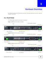
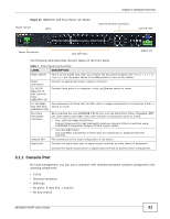
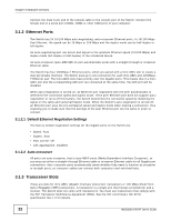
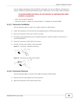
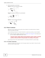
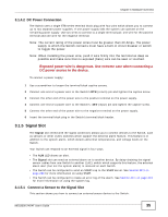
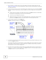
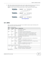
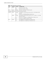
Chapter 3 Hardware Overview 3.1.4.2 DC Power Connection The Switch uses a single ETB series terminal block plug with four pins which allows you to connect up to two separate power supplies. If one power supply fails the system can operate on the remaining power supply. Use two wires to connect to a single terminal pair, one wire for the positive terminal and one wire for the negative terminal. Note: The current rating of the power wires must be greater than 20 Amps. The power supply to which the Switch connects must have a built-in circuit breaker or switch to toggle the power. Note: When installing the power wire, push it wire firmly into the terminal as deep as possible and make sure that no exposed (bare) wire can be seen or touched. Exposed power wire is dangerous. Use extreme care when connecting a DC power source to the device. To connect a power supply: 1 Use a screwdriver to loosen the terminal block captive screws. 2 Connect one end of a power wire to the Switch's RTN (return) pin and tighten the captive screw. 3 Connect the other end of the power wire to the positive terminal on the power supply. 4 Connect one end of a power wire to the Switch's -48V (input) pin and tighten the captive screw. 5 Connect the other end of the power wire to the negative terminal on the power supply. 6 Insert the terminal block plug in the Switch's terminal block header. 3.1.5 Signal Slot The Signal slot (fitted with the signal connector) allows you to connect devices to the Switch, such as sensors or other ZyXEL switches which support the external alarm feature. This feature is in addition to the system alarm, which detects abnormal temperatures, and voltage levels on the Switch. Your Switch can respond to an external signal in four ways. • The ALM LED shows an alert. • The Signal slot can send an external alarm on to another device. By daisy-chaining the signal sensor cables from one Switch to another ZyXEL switch which supports this feature, the external alarm alert (but not the system alarm) is received on each Switch. • The Switch can be configured to send an SNMP trap to the SNMP server. See Section 38.3 on page 290 for more information on using SNMP. • The Switch can be configured to create an error log of the alarm. See Section 40.1 on page 313 for more information on using the system log. 3.1.5.1 Connect a Sensor to the Signal Slot This section shows you how to connect an external sensor device to the Switch. MES3500-24/24F User's Guide 35
-
 1
1 -
2
-
3
-
4
-
5
-
6
-
7
-
8
-
9
-
10
-
11
-
12
-
13
-
14
-
15
-
16
-
17
-
18
-
19
-
20
-
21
-
22
-
23
-
24
-
25
-
26
-
27
-
28
-
29
-
 30
30 -
 31
31 -
 32
32 -
 33
33 -
 34
34 -
 35
35 -
 36
36 -
 37
37 -
 38
38 -
 39
39 -
 40
40 -
41
-
42
-
43
-
44
-
45
-
46
-
47
-
48
-
49
-
50
-
51
-
52
-
53
-
54
-
55
-
56
-
57
-
58
-
59
-
60
-
61
-
62
-
63
-
64
-
65
-
66
-
67
-
68
-
69
-
70
-
71
-
72
-
73
-
74
-
75
-
76
-
77
-
78
-
79
-
80
-
81
-
82
-
83
-
84
-
85
-
86
-
87
-
88
-
89
-
90
-
91
-
92
-
93
-
94
-
95
-
96
-
97
-
98
-
99
-
100
-
101
-
102
-
103
-
104
-
105
-
106
-
107
-
108
-
109
-
110
-
111
-
112
-
113
-
114
-
115
-
116
-
117
-
118
-
119
-
120
-
121
-
122
-
123
-
124
-
125
-
126
-
127
-
128
-
129
-
130
-
131
-
132
-
133
-
134
-
135
-
136
-
137
-
138
-
139
-
140
-
141
-
142
-
143
-
144
-
145
-
146
-
147
-
148
-
149
-
150
-
151
-
152
-
153
-
154
-
155
-
156
-
157
-
158
-
159
-
160
-
161
-
162
-
163
-
164
-
165
-
166
-
167
-
168
-
169
-
170
-
171
-
172
-
173
-
174
-
175
-
176
-
177
-
178
-
179
-
180
-
181
-
182
-
183
-
184
-
185
-
186
-
187
-
188
-
189
-
190
-
191
-
192
-
193
-
194
-
195
-
196
-
197
-
198
-
199
-
200
-
201
-
202
-
203
-
204
-
205
-
206
-
207
-
208
-
209
-
210
-
211
-
212
-
213
-
214
-
215
-
216
-
217
-
218
-
219
-
220
-
221
-
222
-
223
-
224
-
225
-
226
-
227
-
228
-
229
-
230
-
231
-
232
-
233
-
234
-
235
-
236
-
237
-
238
-
239
-
240
-
241
-
242
-
243
-
244
-
245
-
246
-
247
-
248
-
249
-
250
-
251
-
252
-
253
-
254
-
255
-
256
-
257
-
258
-
259
-
260
-
261
-
262
-
263
-
264
-
265
-
266
-
267
-
268
-
269
-
270
-
271
-
272
-
273
-
274
-
275
-
276
-
277
-
278
-
279
-
280
-
281
-
282
-
283
-
284
-
285
-
286
-
287
-
288
-
289
-
290
-
291
-
292
-
293
-
294
-
295
-
296
-
297
-
298
-
299
-
300
-
301
-
302
-
303
-
304
-
305
-
306
-
307
-
308
-
309
-
310
-
311
-
312
-
313
-
314
-
315
-
316
-
317
-
318
-
319
-
320
-
321
-
322
-
323
-
324
-
325
-
326
-
327
-
328
-
329
-
330
-
331
-
332
-
333
-
334
-
335
-
336
-
337
-
338
-
339
-
340
-
341
-
342
-
343
-
344
-
345
-
346
-
347
-
348
-
349
 |
 |