2009 Chrysler Aspen Owner Manual Supplement Hybrid - Page 107
2009 Chrysler Aspen Manual

Page 107 highlights
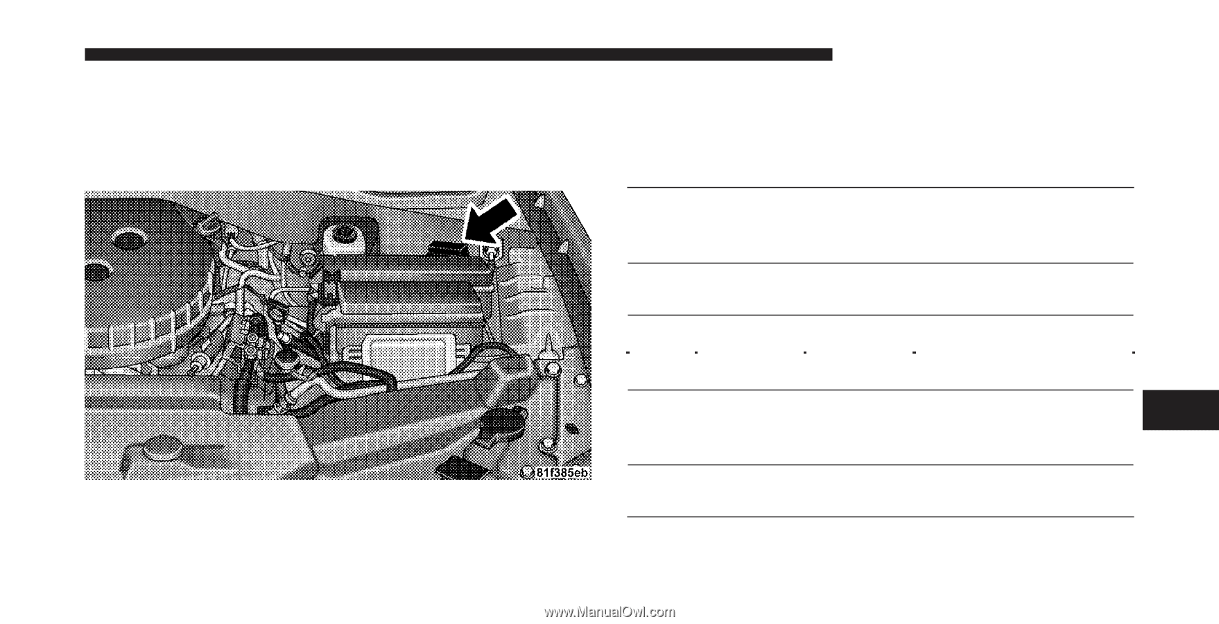
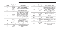
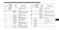
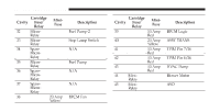
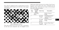
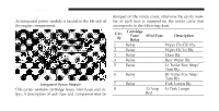
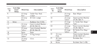
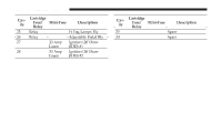
MAINTAINING YOUR VEHICLE 105 Power Distribution Center 2 Your vehicle is equipped with a second electrical power distribution center located in the left side of the engine compartment. inside cover, otherwise the cavity number of each fuse is stamped on the inside cover that corresponds to the following chart. These fuses and relays can be obtained from your authorized dealer. Cavity 1 2 Cartridge Fuse/ Maxi-Fuse Description Relay Solid State Electric Vacuum Relay Pump 40 Amp Transmission Pump Orange Control Module (TPCM) 25 Amp Electric Vacuum Circuit Pump Breaker 80 Amp Electric Power SteerNatural ing 3 7 4 Power Distribution Center 2 This center contains maxi fuses and a relay. A description of each fuse and component may be stamped on the
-
 1
1 -
2
-
3
-
4
-
5
-
6
-
7
-
8
-
9
-
10
-
11
-
12
-
13
-
14
-
15
-
16
-
17
-
18
-
19
-
20
-
21
-
22
-
23
-
24
-
25
-
26
-
27
-
28
-
29
-
30
-
31
-
32
-
33
-
34
-
35
-
36
-
37
-
38
-
39
-
40
-
41
-
42
-
43
-
44
-
45
-
46
-
47
-
48
-
49
-
50
-
51
-
52
-
53
-
54
-
55
-
56
-
57
-
58
-
59
-
60
-
61
-
62
-
63
-
64
-
65
-
66
-
67
-
68
-
69
-
70
-
71
-
72
-
73
-
74
-
75
-
76
-
77
-
78
-
79
-
80
-
81
-
82
-
83
-
84
-
85
-
86
-
87
-
88
-
89
-
90
-
91
-
92
-
93
-
94
-
95
-
96
-
97
-
98
-
99
-
100
-
101
-
 102
102 -
 103
103 -
 104
104 -
 105
105 -
 106
106 -
 107
107 -
 108
108 -
 109
109 -
 110
110 -
 111
111 -
 112
112 -
113
-
114
-
115
-
116
-
117
-
118
-
119
-
120
-
121
-
122
-
123
-
124
-
125
-
126
-
127
-
128
-
129
-
130
-
131
-
132
-
133
-
134
-
135
-
136
-
137
-
138
 |
 |