2013 Ford E350 Super Duty Passenger Owner Manual Printing 3 - Page 276
2013 Ford E350 Super Duty Passenger Manual

Page 276 highlights
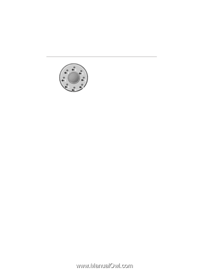
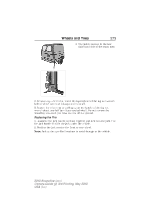
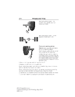
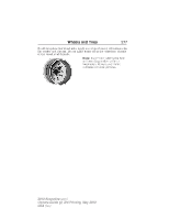
Wheels and Tires 1 6 4 8 2 11. Unblock the wheels. 275 7 3 5 8. Remove the jack and fully tighten the lug nuts in the following pattern. See Wheel Lug Nut Torque Specifications in this chapter for the proper lug nut torque specification. 9. Install any wheel covers, ornaments or hub caps. Make sure they are snapped in place. 10. Stow the jack, handle and lug wrench. Stowing the Flat or Spare Tire Note: Failure to follow spare tire stowage instructions may result in failure of cable or loss of spare tire. 1. Lay the tire on the ground with the valve stem facing in the direction specified on the Tire Changing Instructions located with the jack hardware. 2. Slide the wheel partially under the vehicle and install the retainer through the wheel center. Pull on the cable to align the components at the end of the cable. 3. Turn the jack handle clockwise until the tire is raised to its stowed position underneath the vehicle. The effort to turn the jack handle increases significantly and the spare tire carrier ratchets or slips when the tire is raised to the maximum tightness. Tighten to the best of your ability, to the point where the ratchet/slip occurs, if possible. The spare tire carrier will not allow you to overtighten. If the spare tire carrier ratchets or slips with little effort, take the vehicle to your authorized dealer for assistance at your earliest convenience. 4. Check that the tire lies flat against the frame and is properly tightened. Try to push or pull, then turn the tire to be sure it will not move. Loosen and retighten, if necessary. Failure to properly stow the spare tire may result in failure of the winch cable and loss of the tire. 5. Repeat this tightness check procedure when servicing the spare tire pressure (every six months, as per your scheduled maintenance information), or at any time that the spare tire is disturbed through service of other components. 6. If removed, install the spare tire lock into the bumper drive tube with the spare tire lock key and jack handle. 2013 Econoline (eco) Owners Guide gf, 3rd Printing, May 2013 USA (fus)
-
 1
1 -
2
-
3
-
4
-
5
-
6
-
7
-
8
-
9
-
10
-
11
-
12
-
13
-
14
-
15
-
16
-
17
-
18
-
19
-
20
-
21
-
22
-
23
-
24
-
25
-
26
-
27
-
28
-
29
-
30
-
31
-
32
-
33
-
34
-
35
-
36
-
37
-
38
-
39
-
40
-
41
-
42
-
43
-
44
-
45
-
46
-
47
-
48
-
49
-
50
-
51
-
52
-
53
-
54
-
55
-
56
-
57
-
58
-
59
-
60
-
61
-
62
-
63
-
64
-
65
-
66
-
67
-
68
-
69
-
70
-
71
-
72
-
73
-
74
-
75
-
76
-
77
-
78
-
79
-
80
-
81
-
82
-
83
-
84
-
85
-
86
-
87
-
88
-
89
-
90
-
91
-
92
-
93
-
94
-
95
-
96
-
97
-
98
-
99
-
100
-
101
-
102
-
103
-
104
-
105
-
106
-
107
-
108
-
109
-
110
-
111
-
112
-
113
-
114
-
115
-
116
-
117
-
118
-
119
-
120
-
121
-
122
-
123
-
124
-
125
-
126
-
127
-
128
-
129
-
130
-
131
-
132
-
133
-
134
-
135
-
136
-
137
-
138
-
139
-
140
-
141
-
142
-
143
-
144
-
145
-
146
-
147
-
148
-
149
-
150
-
151
-
152
-
153
-
154
-
155
-
156
-
157
-
158
-
159
-
160
-
161
-
162
-
163
-
164
-
165
-
166
-
167
-
168
-
169
-
170
-
171
-
172
-
173
-
174
-
175
-
176
-
177
-
178
-
179
-
180
-
181
-
182
-
183
-
184
-
185
-
186
-
187
-
188
-
189
-
190
-
191
-
192
-
193
-
194
-
195
-
196
-
197
-
198
-
199
-
200
-
201
-
202
-
203
-
204
-
205
-
206
-
207
-
208
-
209
-
210
-
211
-
212
-
213
-
214
-
215
-
216
-
217
-
218
-
219
-
220
-
221
-
222
-
223
-
224
-
225
-
226
-
227
-
228
-
229
-
230
-
231
-
232
-
233
-
234
-
235
-
236
-
237
-
238
-
239
-
240
-
241
-
242
-
243
-
244
-
245
-
246
-
247
-
248
-
249
-
250
-
251
-
252
-
253
-
254
-
255
-
256
-
257
-
258
-
259
-
260
-
261
-
262
-
263
-
264
-
265
-
266
-
267
-
268
-
269
-
270
-
 271
271 -
 272
272 -
 273
273 -
 274
274 -
 275
275 -
 276
276 -
 277
277 -
 278
278 -
 279
279 -
 280
280 -
 281
281 -
282
-
283
-
284
-
285
-
286
-
287
-
288
-
289
-
290
-
291
-
292
-
293
-
294
-
295
-
296
-
297
-
298
-
299
-
300
-
301
-
302
-
303
-
304
-
305
-
306
-
307
-
308
-
309
-
310
-
311
-
312
-
313
-
314
-
315
-
316
-
317
-
318
-
319
-
320
-
321
-
322
-
323
-
324
-
325
-
326
-
327
-
328
-
329
-
330
-
331
-
332
-
333
-
334
-
335
-
336
-
337
-
338
-
339
-
340
-
341
-
342
-
343
-
344
-
345
-
346
-
347
-
348
-
349
-
350
-
351
-
352
-
353
-
354
-
355
-
356
-
357
-
358
-
359
-
360
-
361
-
362
-
363
-
364
-
365
-
366
-
367
-
368
-
369
-
370
-
371
-
372
-
373
-
374
-
375
-
376
-
377
-
378
-
379
-
380
-
381
-
382
-
383
-
384
-
385
-
386
-
387
-
388
-
389
-
390
-
391
-
392
-
393
-
394
-
395
-
396
-
397
-
398
-
399
-
400
-
401
-
402
-
403
-
404
-
405
-
406
-
407
-
408
-
409
-
410
-
411
-
412
-
413
-
414
-
415
-
416
-
417
-
418
-
419
-
420
-
421
-
422
-
423
-
424
-
425
-
426
-
427
-
428
-
429
-
430
-
431
-
432
-
433
-
434
-
435
-
436
-
437
-
438
-
439
-
440
-
441
-
442
-
443
-
444
 |
 |