3Com 3CDSG10PWR User Guide
3Com 3CDSG10PWR - OfficeConnect Managed Gigabit PoE Switch Manual
 |
UPC - 662705520902
View all 3Com 3CDSG10PWR manuals
Add to My Manuals
Save this manual to your list of manuals |
3Com 3CDSG10PWR manual content summary:
- 3Com 3CDSG10PWR | User Guide - Page 1
3Com® OfficeConnect Managed Gigabit PoE Switch User Guide 3CDSG10PWR www.3Com.com Part Number 10016182 Rev. AA Published July 2007 - 3Com 3CDSG10PWR | User Guide - Page 2
at any time. If there is any software on removable media described in this documentation conjunction with, this User Guide. Unless otherwise indicated, 3Com registered trademarks are countries, licensed exclusively through X/Open Company, Ltd. IEEE and 802 comes from sustainable, managed forests; it - 3Com 3CDSG10PWR | User Guide - Page 3
to the User Guide. The User Guide provides the following sections: ■ Getting Started - Provides introductory information about the Switch OfficeConnect Managed Gigabit PoE and how it can be used in your network. It covers summaries of hardware and software features. ■ Using the 3Com Web Interface - 3Com 3CDSG10PWR | User Guide - Page 4
defining Quality of Service, including DSCP and CoS mapping, policies, and configuring Trust mode. ■ Managing System Files - Provides information for defining file maintenance. ■ Managing Power over Ethernet Devices - Provides information for configuring ports for PoE. ■ Managing System Logs - 3Com 3CDSG10PWR | User Guide - Page 5
you to potential personal injury. Related Documentation In addition to this guide, other documentation available for the 3Com® OfficeConnect Managed Gigabit PoE Switch include the following: ■ Safety and Support Information: Provides installation, set-up, and regulatory compliance information. - 3Com 3CDSG10PWR | User Guide - Page 6
Port 23 Manually set the IP Address using the Console Port 24 Viewing IP Information using the Console Port 25 Setting Up Web Interface Management 27 Web Management Over the Network 28 Setting Up SNMP Management V1 or V2 28 Default Users and Passwords 29 Upgrading Software using the CLI - 3Com 3CDSG10PWR | User Guide - Page 7
Device Representation 35 Using the 3Com Web Interface Management Buttons 35 Using Screen and Table Options 36 Saving the Configuration 40 Resetting the Device 41 Restoring Factory Defaults 43 Logging Off the Device 44 3 VIEWING BASIC SETTINGS Viewing Device Settings 46 Viewing Color Keys 48 - 3Com 3CDSG10PWR | User Guide - Page 8
Storm 86 5 MANAGING SYSTEM INFORMATION Viewing System Description 89 Defining System Settings 91 Configuring System Name 92 Configuring System Time 93 Saving the Device Configuration 96 Resetting the Device 97 6 CONFIGURING PORTS Viewing Port Settings 99 Defining Port Settings 102 Viewing - 3Com 3CDSG10PWR | User Guide - Page 9
INFORMATION Defining IP Addressing 126 Configuring ARP Settings 127 Viewing ARP Settings 128 Defining ARP Settings 129 Removing ARP Entries 130 Configuring Address Tables 132 Viewing Address Table Settings 133 Viewing Port Summary Settings 134 Adding MAC Addresses to the Address Table 136 - 3Com 3CDSG10PWR | User Guide - Page 10
Port Definitions 179 Viewing the OUI Summaries 180 Modifying OUI Definitions 182 14 MANAGING SYSTEM FILES Backing Up System Files 186 Restoring Files 187 Restore the Software Image 188 Activating Image Files 189 15 MANAGING POWER OVER ETHERNET DEVICES Viewing PoE Settings 191 Defining PoE - 3Com 3CDSG10PWR | User Guide - Page 11
216 Switch Features 216 C PIN-OUTS Null Modem Cable 221 PC-AT Serial Cable 221 Modem Cable 222 Ethernet Port RJ-45 Pin Assignments 222 D TROUBLESHOOTING Problem Management 224 Troubleshooting Solutions 224 E 3COM CLI REFERENCE GUIDE Getting Started with the Command Line Interface 227 Console - 3Com 3CDSG10PWR | User Guide - Page 12
235 Logout 236 Password 237 F GLOSSARY ...238 G OBTAINING SUPPORT FOR YOUR 3COM PRODUCTS Register Your Product to Gain Service Benefits 244 Solve Problems Online 244 Purchase Extended Warranty and Professional Services 244 Access Software Downloads 245 Contact Us 245 Telephone Technical - 3Com 3CDSG10PWR | User Guide - Page 13
Specifications ■ Installing the Switch ■ Setting Up for Management ■ Methods of Managing a Switch ■ Switch Setup Overview ■ Using the Command Line Interface (CLI) ■ Setting Up Web Interface Management ■ Setting Up SNMP Management V1 or V2 ■ Default Users and Passwords ■ Upgrading Software using - 3Com 3CDSG10PWR | User Guide - Page 14
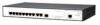
network. The OfficeConnect Managed Gigabit PoE Switch includes the following model: ■ OfficeConnect Managed Gigabit PoE Switch 10-Port The OfficeConnect Managed Gigabit PoE Switch features the following advantages: ■ Full Gigabit speed access ports ■ Jumbo frames support ■ Port security ■ Link - 3Com 3CDSG10PWR | User Guide - Page 15
) Feature OfficeConnect Managed Gigabit PoE Switch Traffic Prioritization Supported (using the IEEE Std 802.ID, 1998 Edition): Eight traffic queues per port Ethernet, Fast Ethernet, Auto-negotiating 10/100/1000BASE-T ports and Gigabit Ethernet Ports SFP Ethernet Ports Supports fiber Gigabit - 3Com 3CDSG10PWR | User Guide - Page 16
the LEDs. Table 2 Description on the LEDs of the OfficeConnect Managed Gigabit PoE Switch LED Power Label Power 10/100/1000 BASE-T Ethernet port status Link/ Activity Duplex mode Duplex 1000Base SFP Module port status Present PoE status PoE Status Status Green Yellow OFF Green Yellow OFF - 3Com 3CDSG10PWR | User Guide - Page 17
Switch OfficeConnect Managed Gigabit PoE series switch Specification Physical dimensions (H×W×D) Weight Console port Gigabit Ethernet ports on the front panel AC Input voltage Power consumption (full load) Operating temperature Relative humidity Switch OfficeConnect Managed Gigabit PoE 3CDSG10PWR - 3Com 3CDSG10PWR | User Guide - Page 18
set up your 3Com switch. WARNING: Safety Information. Before you install or remove any components from the Switch or carry out any maintenance procedures, you must read the 3Com Switch stwie zawartymi w 3Com Switch Family Safety and Regulatory Information. CAUTION Opening the switch or tampering with - 3Com 3CDSG10PWR | User Guide - Page 19
the Console port for basic operations of the switch including setting and viewing the IP address, configuring user accounts, upgrading switch firmware, and more. Refer to "3Com CLI Reference Guide" on page 227. Web Interface Each switch has an internal set of web pages that allow you to manage - 3Com 3CDSG10PWR | User Guide - Page 20
software, available from the 3Com website. Figure 3 SNMP Management over the Network Switch Setup Overview Refer to "Setting Up SNMP Management V1 or V2" on page 28. This section gives an overview of what you need to do to get your switch set up and ready for management when it is in its default - 3Com 3CDSG10PWR | User Guide - Page 21
page 27 Refer to the label on the rear of the switch which details the default IP address. Connect to the console port and use the Command Line Interface. See page 25 Feature Management How do you want to manage your Switch? See page 19 Command Line Interface (basic setup only) Connect using - 3Com 3CDSG10PWR | User Guide - Page 22
IP address, instead of you having to manually reconfigure the switch. If you use the automatic IP configuration method, you need to discover the automatically allocated IP information before you can begin management. Work through the "Viewing IP Information using the Console Port" on page 25. Manual - 3Com 3CDSG10PWR | User Guide - Page 23
Command Line Interface (CLI) You can access the switch through the Console port to manually set the IP address, or to view the IP address that was assigned automatically (for example, by a DHCP server). For more information about the CLI, refer to "3Com CLI Reference Guide" on page 227. Connecting - 3Com 3CDSG10PWR | User Guide - Page 24
software for more information. 3 Power up the switch. The Power on Self Test (POST) will be performed. The OfficeConnect Managed Gigabit PoE Switch takes approximately one minute to boot. Manually set the IP Address using the Console Port You are now ready to manually set up the switch with IP - 3Com 3CDSG10PWR | User Guide - Page 25
the logout command to terminate the CLI session. The initial setup of your switch is now complete and the switch is ready for you to set up your chosen management method. See "Methods of Managing a Switch" on page 19. Viewing IP Information using the Console Port This section describes how to view - 3Com 3CDSG10PWR | User Guide - Page 26
for you to set up your chosen management method. See "Methods of Managing a Switch" on page 19. For more information about the CLI, refer to "3Com CLI Reference Guide" on page 227. If you do not intend to use the command line interface using the console port to manage the switch, you can logout - 3Com 3CDSG10PWR | User Guide - Page 27
Up Web Interface Management 27 Setting Up Web Interface Management This section describes how you can set up web interface management over the network. Prerequisites ■ Ensure you have already set up the switch with IP information as described in "Methods of Managing a Switch" on page 19. ■ Ensure - 3Com 3CDSG10PWR | User Guide - Page 28
the default passwords). The main Web interface page is displayed. Setting Up SNMP Management V1 or V2 You can use any network management application running the Simple Network Management Protocol (SNMP) to manage the switch. 3Com offers a range of network management applications to address - 3Com 3CDSG10PWR | User Guide - Page 29
aaa is the IP address of the TFTP server and bbb is the source bootcode filename. The bootcode firmware may not require upgrading for every software upgrade, therefore there may not be a new bootcode file to download. 3 To set the switch to boot from the new software you have downloaded, enter the - 3Com 3CDSG10PWR | User Guide - Page 30
2 USING THE 3COM WEB INTERFACE This section provides an introduction to the user interface, and includes the following topics: ■ Starting the 3Com Web Interface ■ Understanding the 3Com Web Interface ■ Saving the Configuration ■ Resetting the Device ■ Restoring Factory Defaults ■ Logging Off the - 3Com 3CDSG10PWR | User Guide - Page 31
the local database. A unique password is required of each user. Two access levels exist on the 3Com Web Interface: ■ Management access level - Provides the user with read/write access. There is always one management level user configured for the switch. The factory default is be username: admin with - 3Com 3CDSG10PWR | User Guide - Page 32
To access the 3Com user interface: 1 Open an Internet browser. 2 Enter the device IP address in the address bar and press Enter. The Enter Network Password Page opens: Figure 6 Enter Network Password Page 3 Enter your user name and password. The device default factory settings is configured with - 3Com 3CDSG10PWR | User Guide - Page 33
The 3Com Web Interface Home Page contains the following views: ■ Tab View - Provides the device summary configuration located at the top of the home page. ■ Tree View - Provides easy navigation through the configurable device features. The main branches expand to display the sub-features. ■ Port - 3Com 3CDSG10PWR | User Guide - Page 34
device features. Click the tabs to view all the components under a specific feature. Provides access to online help, and contains information about the user interface buttons, including both management buttons and task icons. ■ Using the 3Com Web Interface Management Buttons - Provides instructions - 3Com 3CDSG10PWR | User Guide - Page 35
Figure 9 Device Representation 2 By selecting a specific port with your mouse, you can view the port statistics. For detailed information on configuring ports, please refer to Configuring Ports. Using the 3Com Web Interface Management Buttons Configuration Management buttons and icons provide an - 3Com 3CDSG10PWR | User Guide - Page 36
INTERFACE Using Screen and Table Options 3Com contains screens and tables for configuring devices. This section contains the following topics: ■ To view configuration information: 1 Click Port > Administration > Summary. The Port Settings Summary Page opens: Figure 10 Port Settings Summary Page - 3Com 3CDSG10PWR | User Guide - Page 37
and Table Options 37 Adding Configuration Information User-defined information can be added to specific 3Com Web Interface pages, by opening the IP Setup Page. To configure IP Setup: 1 Click Administration > IP Setup. The IP Setup Page opens: Figure 11 IP Setup Page 2 Enter requisite information in - 3Com 3CDSG10PWR | User Guide - Page 38
38 CHAPTER 2: USING THE 3COM WEB INTERFACE Modifying Configuration Information 1 Click Administration > System Access > Modify. The System Access Modify Page opens: Figure 12 System Access Modify Page 2 Modify the fields. 3 Click . The access fields are modified. - 3Com 3CDSG10PWR | User Guide - Page 39
Using Screen and Table Options 39 Removing Configuration Information 1 Click Administration > System Access > Remove. The System Access Remove Page opens: Figure 13 System Access Remove Page 2 Select the user account to be deleted. 3 Click . The user account is deleted, and the device is updated. - 3Com 3CDSG10PWR | User Guide - Page 40
only saved to the device once the user saves the changes to the flash memory. The Save Configuration tab allows the latest configuration to be saved to the flash memory. To save the device configuration: 1 Click Save Configuration. The Save Configuration Page opens: Figure 14 Save Configuration Page - 3Com 3CDSG10PWR | User Guide - Page 41
current configuration from being lost, use the Save Configuration Page to save all user-defined changes to the flash memory before resetting the device. To reset the device: 1 Click Administration > Reset. The Reset Page opens: Figure 15 Reset Page 2 Click . A confirmation message is displayed. - 3Com 3CDSG10PWR | User Guide - Page 42
42 CHAPTER 2: USING THE 3COM WEB INTERFACE 3 Click . The device is reset, and a prompt for a user name and password is displayed. Figure 16 User Name and Password Page 4 Enter a user name and password to reconnect to the web interface. - 3Com 3CDSG10PWR | User Guide - Page 43
Reset Page opens: Figure 17 Reset Page The Reset Page contains the following fields: ■ Initialize with Current IP Address - Resets the device with the factory default settings, but maintains the current IP Address. ■ Initialize with Default IP Address - Resets the device with the factory default - 3Com 3CDSG10PWR | User Guide - Page 44
44 CHAPTER 2: USING THE 3COM WEB INTERFACE Logging Off the Device To log off the device: 1 Click . The Logout Page opens. 2 The following message appears: 3 Click . The 3Com Web Interface Home Page closes. - 3Com 3CDSG10PWR | User Guide - Page 45
contains information for viewing basic settings. The 3Com Web Interface Home Page presents a device summary section that provides the system administrator with the option to view essential information required for setting up and maintaining device settings. The Device Summary Section contains - 3Com 3CDSG10PWR | User Guide - Page 46
MAC addresses, and both software, boot, and hardware versions. To view the Device Summary Settings: 1 Click Device Summary. The Device Summary Page opens: Figure 18 Device Summary Page The Device Summary Page contains the following fields: ■ Product Description - Displays the device model number - 3Com 3CDSG10PWR | User Guide - Page 47
- Displays the vendor's authoritative identification of the network management subsystem contained in the entity. ■ MAC Address - Displays the device MAC address. ■ System Up Time - Displays the amount of time since the most recent device reset. The system time is displayed in the following format - 3Com 3CDSG10PWR | User Guide - Page 48
Color Key Page opens: Figure 19 Color Key Page The Color Key Page contains the following fields: ■ RJ45 - Displays the port status of the . ■ Light Gray - Port has been set to inactive by User or Protocol. ■ Dark Blue - Port has been selected by user. ■ Red - Port or Transceiver has failed POST - 3Com 3CDSG10PWR | User Guide - Page 49
The Management Security section provides information for configuring system access, defining RADIUS authentication, port-based authentication and defining access control lists. This section includes the following topics: ■ Configuring System Access ■ Defining RADIUS Clients ■ Defining Port-Based - 3Com 3CDSG10PWR | User Guide - Page 50
is always one management level user configured for the switch. The factory default user name is: admin with no password. ■ Monitor access level - Provides the user with read-only system access. This section contains the following topics: ■ Viewing System Access Settings ■ Defining System Access - 3Com 3CDSG10PWR | User Guide - Page 51
System The System Access Summary Page displays the current users and access Access Settings levels defined on the device. To view System Access settings: 1 Click Administration > System Access > Summary. The System Access Summary Page opens: Figure 20 System Access Summary Page The System Access - 3Com 3CDSG10PWR | User Guide - Page 52
Level - Defines the user access level. The lowest user access level is Monitor and the highest is Management. ■ Management - Provides users with read and write access rights. ■ Monitor - Provides users with read access rights. ■ Password - Defines the user password. User passwords can contain up - 3Com 3CDSG10PWR | User Guide - Page 53
with read access rights. ■ Password Modify - Enables modifying a password for an existing user. ■ Password - Defines the local user password. Local user passwords can contain up to 10 characters. ■ Confirm Password - Verifies the password. 2 Select a User Name whose settings are to be modified - 3Com 3CDSG10PWR | User Guide - Page 54
removed can be selected from the list below. ■ User Name - Displays the user name. ■ Access Level - Displays the user access level. The lowest user access level is Monitoring and the highest is Management. ■ Management - Provides users with read and write access rights. ■ Monitoring - Provides - 3Com 3CDSG10PWR | User Guide - Page 55
Setup Page opens: Figure 24 Radius Client Setup Page The Radius Client Setup Page contains the following fields: ■ Primary Server - Defines the RADIUS Primary Server authentication fields. ■ Backup Server - Defines the RADIUS Backup Server authentication fields. ■ Host IP Address - Defines the - 3Com 3CDSG10PWR | User Guide - Page 56
server before retrying the query, or switching to the next server. Possible field values are 1-30. The default value is 3. ■ Dead Time - Defines the default amount of time (in minutes) that a RADIUS server is bypassed for service requests. The range is 0-2000. The default value is 0. ■ Key String - 3Com 3CDSG10PWR | User Guide - Page 57
Port-Based Authentication (802.1X) Port-based authentication authenticates users on a per-port basis via an external server. Only authenticated and approved system users can transmit and receive data. Ports is authorized to access system services. Port-based authentication creates two access states - 3Com 3CDSG10PWR | User Guide - Page 58
58 CHAPTER 4: MANAGING DEVICE SECURITY Viewing 802.1X The 802.1X Summary Page allows the network administrator to view Authentication port-based authentication settings. To view Port-based Authentication: 1 Click Security > 802.1X > Summary. The 802.1X Summary Page opens: Figure 25 802.1X Summary - 3Com 3CDSG10PWR | User Guide - Page 59
Reauthentication - Indicates if periodic reauthentication is enabled on the port. ■ Enable - Periodic reauthentication is enabled on the port. ■ Disable - Periodic reauthentication is disabled on the port. This is the default. ■ Reauthentication Period - Displays the time span (in seconds) in - 3Com 3CDSG10PWR | User Guide - Page 60
for configuring 802.1X Authentication global settings on the device and defining specific 802.1X setting for each port individually. Monitor users have no access to this page. To configure 802.1X Settings: 1 Click Security > 802.1X > Setup. The 802.1X Setup Page opens: Figure 26 802.1X Setup Page - 3Com 3CDSG10PWR | User Guide - Page 61
users. ■ Guest VLAN ID - Specifies the guest VLAN ID. 802.1X Port Settings ■ Admin Port Control - Specifies the admin port authorization state. ■ Auto - Enables port services to the client through the interface. ■ Guest VLAN - Specifies whether the Guest VLAN is enabled on the port. - 3Com 3CDSG10PWR | User Guide - Page 62
Access Control Lists (ACLs) allow network managers to define classification actions and rules for specific ingress ports. Packets entering an ingress port, with an active ACL are either admitted or denied entry. If they are denied entry, the user can disable the port. For example, an ACL rule is - 3Com 3CDSG10PWR | User Guide - Page 63
are reactivated from the Port Administration Setup Page. To view MAC Based ACLs: 1 Click Device > ACL > MAC Based ACL > Summary. The MAC Based ACL Summary Page opens: Figure 27 MAC Based ACL Summary Page The MAC Based ACL Summary Page contains the following fields: ■ ACL Name - Contains a list of - 3Com 3CDSG10PWR | User Guide - Page 64
to which the packet was addressed. Ports are reactivated from the Port Administration Setup Page. Configuring MAC The MAC Based ACL Setup Page allows the network administrator to Based ACLs create and define rules for MAC-based ACLs. Monitor users have no access to this page. To configure MAC-based - 3Com 3CDSG10PWR | User Guide - Page 65
added. ■ Create ACL - Defines a new user-defined MAC-based Access Control List. Add Rules to ACL ■ Priority - Sets the rule priority, which determines which rule is indicates that all bits are important. For example, if the destination MAC address is 00:AB:22:11:33:00 and the wildcard mask is 00 - 3Com 3CDSG10PWR | User Guide - Page 66
- Drops packet that meets the ACL criteria, and disables the port to which the packet was addressed. Ports are reactivated from the Port Administration Setup Page. To create a new MAC-based ACL: ACL rule. 4 Click . The new MAC-based ACL rule settings are configured, and the device is updated. - 3Com 3CDSG10PWR | User Guide - Page 67
an existing MAC-based ACL rule. Monitor users have no access to this page. To > Modify. The MAC Based ACL Modify Page opens: Figure 29 MAC Based ACL Modify Page The MAC Address - Defines the source MAC address to which packets are addressed to the rule. ■ Source Mask - Defines the source MAC Address - 3Com 3CDSG10PWR | User Guide - Page 68
ACL criteria. ■ Shutdown - Drops packet that meets the ACL criteria, and disables the port to which the packet was addressed. Ports are reactivated from the Port Administration Setup Page. 2 Define the fields. 3 Click . The MAC-based ACL rule settings are modified, and the device is updated. - 3Com 3CDSG10PWR | User Guide - Page 69
to which packets are addressed to the rule. ■ Destination Address - Matches the destination MAC address to which packets are addressed to the rule. ■ VLAN ID - Matches the packet's VLAN ID to the rule. The possible field values are 1 to 4093. ■ CoS - Classifies Class of Service of the packet. - 3Com 3CDSG10PWR | User Guide - Page 70
- Drops packets which meet the ACL criteria. ■ Shutdown - Drops packet that meets the ACL criteria, and disables the port to which the packet was addressed. Ports are reactivated from the Port Administration Setup Page. To remove MAC-based ACLs: 1 Select the ACL Name to be deleted. 2 Check Remove - 3Com 3CDSG10PWR | User Guide - Page 71
or UDP are selected in the Protocol list. ■ Source Port - Indicates the source port that is matched packets. Enabled only when TCP or UDP are selected in the Protocol list. ■ Flag Set - Indicates the TCP flag to which the packet is mapped. ■ ICMP Type - Indicates the ICMP message type for filtering - 3Com 3CDSG10PWR | User Guide - Page 72
, and disables the port to which the packet was addressed. Ports are reactivated from the Port Administration Setup Page. Defining IP Based ACLs Access Control Lists (ACL) allow network managers to define classification actions and rules for specific ingress ports. Your switch supports up to 256 - 3Com 3CDSG10PWR | User Guide - Page 73
users have no access to this page. To configure IP-based ACLs: Click Device > ACL > IP Based ACL > Setup. The IP Based ACL Setup Page opens: Figure 32 IP Based ACL Setup Page The IP - Adds user-defined protocols by which packets are matched to the rule. Each protocol has a specific protocol number - 3Com 3CDSG10PWR | User Guide - Page 74
MANAGING DEVICE SECURITY ■ Source Port - Defines the source port that is used for matched packets. Enabled only when TCP or UDP are selected in the Protocol list. The field value is either user defined or Any. If Any is selected the IP based ACL is applied to any source port. ■ Destination Port Set - 3Com 3CDSG10PWR | User Guide - Page 75
type. ■ Any - Does not filter for an IGMP message type. ■ Source IP Address - If selected, enables matching the source port IP address to which packets are addressed to the rule, according to a wildcard mask. The field value is either user defined or Any. If Any is selected, accepts any source - 3Com 3CDSG10PWR | User Guide - Page 76
76 CHAPTER 4: MANAGING DEVICE SECURITY wildcard mask matches all IP addresses in the range 149.36.184.0 meets the ACL criteria, and disables the port to which the packet was addressed. Ports are reactivated from the Port Administration Setup Page. To create a new IP-based ACL: 1 Select Create ACL. - 3Com 3CDSG10PWR | User Guide - Page 77
. The IP Based ACL Modify Page opens: Monitor users have no access to this page. Figure 33 IP Based ACL Modify Page The IP Based ACL Modify Page contains the following fields: ■ Select ACL - Selects the ACL to be modified. ■ Select Rule - Displays a table of rules and their settings associated with - 3Com 3CDSG10PWR | User Guide - Page 78
user-defined protocols by which packets are matched to the rule. Each protocol has a specific protocol number which is unique. The possible field range is 0-255. ■ Source Port - Enables creating an ACL based on a specific . ■ Rst - Reset the connection. This ■ Set - Enables the TCP flag. ■ Unset - 3Com 3CDSG10PWR | User Guide - Page 79
values are: ■ Select from List - Selects an IGMP message type from a list. ■ IGMP Type - Specifies an IGMP message type. ■ Any - Does not filter for an IGMP message type. ■ Source IP Address - Matches the source IP address to which packets are addressed to the rule. ■ Wild Card Mask - Defines - 3Com 3CDSG10PWR | User Guide - Page 80
Click . The ACL rule is modified, and the device is updated. Removing IP Based The IP Based ACL Remove Page allows the user to remove IP-based ACLs ACLs or IP-based ACL rules. Monitor users have no access to this page. Click Device > ACL > IP Based ACL > Remove. The IP Based ACL Remove Page opens: - 3Com 3CDSG10PWR | User Guide - Page 81
Name - Selects an ACL name from a list of the IP-based ACLs. ■ Remove ACL - Enables the ACL to be Destination Port - Displays the TCP/UDP destination port. ■ Source Port - Displays the TCP/UDP source port to which the ACL is matched. ■ Flag Set - IGMP Type - Indicates the IGMP message type filter. - 3Com 3CDSG10PWR | User Guide - Page 82
82 CHAPTER 4: MANAGING DEVICE SECURITY ■ Source Address - Indicates the source IP address. ■ Source Mask - Indicates the source IP address mask. ■ Destination Address - Indicates the destination IP address. ■ Destination Mask - Indicates the destination IP address mask. ■ DSCP - Matches the packet - 3Com 3CDSG10PWR | User Guide - Page 83
Control Lists 83 Viewing ACL Binding The ACL Binding Summary Page displays the user-defined ACLs mapped to the interfaces. To view ACL Binding: 1 Click Device > ACL > ACL Binding > Summary. The ACL Binding Summary Page opens: Figure 35 ACL Binding Summary Page The ACL Binding Summary Page contains - 3Com 3CDSG10PWR | User Guide - Page 84
Setup Page allows the network administrator to bind Binding specific ports to MAC- or IP-based ACLs. The monitor user has no access to this page. To define ACL Binding: 1 Click Device > ACL > ACL Binding > Setup. The ACL Binding Setup Page opens: Figure 36 ACL Binding Setup Page The ACL Binding - 3Com 3CDSG10PWR | User Guide - Page 85
administrator to Binding remove user-defined ACLs from a selected interface. Monitor users have no access to this opens: Figure 37 ACL Binding Remove Page The ACL Binding Remove Page contains the following fields: ■ Checkbox (unnamed) - Marks the ACL for removal. ■ Interface - Displays the port - 3Com 3CDSG10PWR | User Guide - Page 86
by defining the packet type and the rate the packets are transmitted. The system measures the incoming Broadcast and Multicast frame rates separately on each port, and discards the frames when the rate exceeds a user-defined rate. Packet threshold is ignored if Broadcast Storm Control is Disabled. - 3Com 3CDSG10PWR | User Guide - Page 87
&Multicast - Enables broadcast and multicast control on the selected port. ■ Packet Rate Threshold (3500-1000000) - Defines the maximum rate (kilobits per second) at which unknown packets are forwarded. The range is 3,500-1,000,000. The default value is 3500. 2 Define the relevant fields. 3 Click - 3Com 3CDSG10PWR | User Guide - Page 88
5 MANAGING SYSTEM INFORMATION This section contains information for configuring general system information, and includes the following: ■ Viewing System Description ■ Defining System Settings ■ Saving the Device Configuration ■ Resetting the Device - 3Com 3CDSG10PWR | User Guide - Page 89
, and MAC addresses, and both software, boot, and hardware versions. To view Device Summary Information: 1 Click Device Summary. The Device View Page opens. Figure 39 Device View Page The Device View Page contains the following fields: ■ Product Description - Displays the device model number and - 3Com 3CDSG10PWR | User Guide - Page 90
- Displays the device MAC address. ■ System Up Time - Displays the amount of time since the most recent device reset. The system time is displayed in the following format: Days, Hours, Minutes, and Seconds. For example, 41 days, 2 hours, 22 minutes and 15 seconds. ■ Software Version - Displays the - 3Com 3CDSG10PWR | User Guide - Page 91
91 Defining System Settings The following section allows system administrators to configure advanced system settings. The section includes the following topics: ■ Configuring System Name ■ Configuring System Time - 3Com 3CDSG10PWR | User Guide - Page 92
System Name: 1 Click Administration > System Name > System Name. The System Name Page opens: Figure 40 System Name Page The System Name Page includes the following fields: ■ System Name - Defines the user-defined device name. The field length is 0-100 characters. ■ System Location - Defines the - 3Com 3CDSG10PWR | User Guide - Page 93
device. Monitor users have limited permissions on this page. To configure the System Time: 1 Click Administration > System Time > Setup. The System Time Setup Page opens: Figure 41 System Time Setup Page The System Time Setup Page contains the following fields: Local Settings ■ Hours - Sets the hour - 3Com 3CDSG10PWR | User Guide - Page 94
MANAGING SYSTEM INFORMATION ■ Daylight Saving - Enables setting automatic Daylight Savings Time (DST) on the device, either on a non-recurring or recurring basis. In the non-recurring case, DST is configured to apply to one specific of November. ■ European - The device switches to DST at 1:00 am on - 3Com 3CDSG10PWR | User Guide - Page 95
which DST ends. The field range is 2000-2037. ■ Recurring - Enables user-defined DST for countries in which DST is constant from year to year, other digit minute. 2 Define the Local Settings time and date fields. 3 To configure the device to automatically switch to DST, select Daylight Saving and - 3Com 3CDSG10PWR | User Guide - Page 96
MANAGING SYSTEM INFORMATION Saving the Device The Save Configuration Page allows the latest device configuration to be Configuration saved to the flash memory. Monitor users have no access to this page. To save the device configuration: 1 Click Save Configuration. The Save Configuration Page opens - 3Com 3CDSG10PWR | User Guide - Page 97
values are: ■ Initialize with Current IP Address - Returns the device to factory defaults, but maintains the current IP address. ■ Initialize with Default IP Address - Returns the device to factory defaults, including the IP address. 2 Define the fields. 3 Click or . The device is reset. - 3Com 3CDSG10PWR | User Guide - Page 98
6 CONFIGURING PORTS This section contains information for configuring Port Settings, and includes the following sections: ■ Viewing Port Settings ■ Defining Port Settings ■ Viewing Port Details - 3Com 3CDSG10PWR | User Guide - Page 99
99 Viewing Port Settings The Port Administration Summary Page permits the network manager to view the current ports configuration. When configuring the port speed and port Duplex mode, please note the following: ■ Setting the port speed to 10/100/1000 and the Duplex mode to Half = admin speed is = - 3Com 3CDSG10PWR | User Guide - Page 100
6: CONFIGURING PORTS To view Port Settings: 1 Click Port > Administration > Summary. The Port Administration Summary Page opens: Figure 44 Port Administration Summary Page The Port Administration Summary Page contains the following fields: ■ Port - Indicates the selected port number. ■ Port Status - 3Com 3CDSG10PWR | User Guide - Page 101
duplex mode. This field is configurable only when auto negotiation is disabled, and the port speed is set to 10M or 100M or 1000M per second. The possible field values are: ■ Full - The interface supports transmission between the device and its link partner in both directions simultaneously. ■ Half - 3Com 3CDSG10PWR | User Guide - Page 102
CONFIGURING PORTS Defining Port The Port Administration Setup Page allows network managers to Settings configure port parameters for specific ports. Monitor users have no access to this page. To configure Port Settings: 1 Click Port > Administration > Setup. The Port Administration Setup Page opens - 3Com 3CDSG10PWR | User Guide - Page 103
. This field is configurable only when auto negotiation is disabled, and the port speed is set to 10M or 100M. The possible field values are: ■ Auto - Use to automatically configure the port. ■ Full - The interface supports transmission between the device and its link partner in both directions - 3Com 3CDSG10PWR | User Guide - Page 104
specific ports. Monitor users have no access to this page. To view Port Details: 1 Click Port > Administration > Detail. The Port Detail Page opens: Figure 46 Port Detail Page The Port Detail Page contains the following fields: ■ Select a port - Selects a port to display its current settings. ■ Port - 3Com 3CDSG10PWR | User Guide - Page 105
only when auto negotiation is disabled, and the port speed is set to 10M or 100M. This field cannot be configured on LAGs. The possible field values are: ■ Auto - Use to automatically configure the port. ■ Full - The interface supports transmission between the device and its link partner in - 3Com 3CDSG10PWR | User Guide - Page 106
the same transceiver type. ■ The device supports up to four LAGs, and eight ports in each LAG. ■ Ports added to a LAG lose their individual port configuration. When ports are removed from the LAG, the original port configuration is applied to the ports. This section contains the following topics - 3Com 3CDSG10PWR | User Guide - Page 107
to form a single LAG. Aggregating ports multiplies the bandwidth between the devices, increases port flexibility, and provides link redundancy. To view Link Aggregation: 1 Click Ports > Link Aggregation > Summary. The Link Aggregation Summary Page opens: Figure 47 Link Aggregation Summary Page - 3Com 3CDSG10PWR | User Guide - Page 108
108 CHAPTER 7: AGGREGATING PORTS Monitor users have no access to this page. To create Link Aggregation: 1 Click Ports > Link Aggregation > Create. The Link Aggregation Create Page opens: Figure 48 Link Aggregation Create Page The Link Aggregation Create Page includes the following fields: ■ Enter - 3Com 3CDSG10PWR | User Guide - Page 109
The field range is 1-4. ■ Type - Displays the type of link aggregation. The possible field values are Static or LACP. ■ Member Ports - Displays the ports configured to the link aggregation. 2 Define the fields. 3 Click . The link aggregation configuration is defined, and the device is updated - 3Com 3CDSG10PWR | User Guide - Page 110
multiplies the bandwidth between the devices, increases port flexibility, and provides link redundancy. Monitor users have no access to this page. To modify Link Aggregation: 1 Click Ports > Link Aggregation > Modify. The Link Aggregation Modify Page opens: Figure 49 Link Aggregation Modify Page - 3Com 3CDSG10PWR | User Guide - Page 111
Group ID. The field range is 1-4. ■ Type - Displays the link aggregation type. The possible field values are Static or LACP. ■ Member Ports - Displays the ports configured to the link aggregation. 2 Define the fields. 3 Click . The link aggregation modified, and the application is updated. - 3Com 3CDSG10PWR | User Guide - Page 112
Aggregation Remove Page allows the network manager to Aggregation remove group IDs containing member ports. Monitor users have no access to this page. To remove Link Aggregation: 1 Click Ports > Link Aggregation > Remove. The Link Aggregation Remove Page opens: Figure 50 Link Aggregation Remove Page - 3Com 3CDSG10PWR | User Guide - Page 113
are operating at the same speed. Aggregated links can be set up manually or automatically established by enabling LACP on the relevant links. Aggregate ports can be linked into link-aggregation port-groups. The LACP Summary Page contains fields for viewing Link Aggregation Group Protocol (LACP) LAGs - 3Com 3CDSG10PWR | User Guide - Page 114
be set up manually or automatically established by enabling LACP on the relevant links. Aggregate ports can be linked into link-aggregation port-groups. The LACP Modify Page contains fields for modifying LACP LAGs. To modify LACP for LAGs: 1 Click Port > LACP > Modify. The LACP Modify Page opens - 3Com 3CDSG10PWR | User Guide - Page 115
115 2 Define the fields. 3 Click . The LACP Link Aggregation is modified, and the application is updated. - 3Com 3CDSG10PWR | User Guide - Page 116
between VLAN groups. VLAN1is the default VLAN and always contains untagged ports. All ports are members of VLAN1 by default. If the untagged port is moved to a new VLAN, the port is removed from VLAN1. For example: If an untagged port 24 is moved to VLAN 5. The port will no longer be a member - 3Com 3CDSG10PWR | User Guide - Page 117
details: 1 Click Device > VLAN > VLAN Detail. The VLAN Detail Page opens: Figure 53 VLAN Detail Page The VLAN Detail Page contains the following information: ■ Select a VLAN to Display- Selects a VLAN to be display its settings. ■ Membership type - Displays the membership type for each VLAN. The - 3Com 3CDSG10PWR | User Guide - Page 118
information on VLAN configured Details ports. To view VLAN Port details: 1 Click Device > VLAN > Port Detail. The VLAN Port Detail Page opens: Figure 54 VLAN Port Detail Page The VLAN Port Detail Page contains the following information: ■ Select Port - Selects the ports to be displayed. ■ Untagged - 3Com 3CDSG10PWR | User Guide - Page 119
VLANs The VLAN Setup Page allows the network administrator to create or rename VLANs. The monitor users have no access to this page. To create VLANs: 1 Click Device > VLAN > Setup. The VLAN Setup Page opens: Figure 55 VLAN Setup Page The VLAN Setup Page contains the following fields: Create ■ VLAN - 3Com 3CDSG10PWR | User Guide - Page 120
VLANS Rename VLAN ■ ID - Displays the VLAN ID selected from the above list. ■ Name - Defines the new VLAN name. ■ Rename - Renames the user-defined VLAN name. 2 Enter the VLAN ID number(s). 3 Click . The VLAN(s) are created, and the device is updated. To rename a VLAN: 1 Highlight - 3Com 3CDSG10PWR | User Guide - Page 121
121 Modifying VLAN The Modify VLAN Page allows the network manager to rename VLANs Settings and change VLAN membership. The monitor users have no access to this page. To edit VLAN Settings: Click Device > VLAN > Modify VLAN. The Modify VLAN Page opens: Figure 56 Modify VLAN Page The Modify VLAN Page - 3Com 3CDSG10PWR | User Guide - Page 122
- Indicates the interface is not available for selection. ■ Select port to add to this VLAN - Adds a selected port to the VLAN. ■ Select All - Allows the user to select all ports to be added to the VLAN. ■ Select None - Removes the ports selected. To rename VLANs: 1 Select a VLAN from the list - 3Com 3CDSG10PWR | User Guide - Page 123
123 Modifying Port VLAN The Modify VLAN Port Page allows the network manager to modify port Settings VLAN settings. The monitor users have no access to this page. To modify Port VLAN Settings: 1 Click Device > VLAN > Modify Port. The Modify VLAN Port Page opens: Figure 57 Modify VLAN Port Page The - 3Com 3CDSG10PWR | User Guide - Page 124
port. 5 Click . The VLANs are configured, and the device is updated. Removing VLANs The VLAN Remove Page allows the network administrator to remove VLANs. The monitor users have no access to this page. To delete VLANs: 1 Click Device > VLAN > Remove. The VLAN Remove Page opens: - 3Com 3CDSG10PWR | User Guide - Page 125
9 CONFIGURING IP AND MAC ADDRESS INFORMATION This section contains information for defining IP interfaces, and includes the following sections: ■ Defining IP Addressing ■ Configuring ARP Settings ■ Configuring Address Tables - 3Com 3CDSG10PWR | User Guide - Page 126
when the IP Address is modified and changed. Packets are forwarded to the default gateway when sent to a remote network. The monitor user has no access to this page. To define an IP interface: 1 Click Administration > IP Setup. The IP Setup Page opens: Figure 59 IP Setup Page The IP Setup Page - 3Com 3CDSG10PWR | User Guide - Page 127
Configuring ARP Settings 127 Configuring ARP Settings The Address Resolution Protocol (ARP) converts IP addresses into physical addresses, and maps the IP address to a MAC address. ARP allows a host to communicate with other hosts when only the IP address of its neighbors is known. This section - 3Com 3CDSG10PWR | User Guide - Page 128
ARP Settings Summary Page opens: Figure 60 ARP Settings Summary Page The ARP Settings Summary Page contains the following fields: ■ Interface - Indicates the VLAN for which ARP parameters are defined. ■ IP Address - Indicates the station IP address, which is associated with the MAC Address. ■ MAC - 3Com 3CDSG10PWR | User Guide - Page 129
ARP Settings The ARP Settings Setup Page allows network managers to define ARP parameters for specific interfaces. The monitor users have no access to this page. To configure ARP entries: 1 Click Administration > ARP Settings > Setup. The ARP Settings Setup Page opens: Figure 61 ARP Settings Setup - 3Com 3CDSG10PWR | User Guide - Page 130
IP AND MAC ADDRESS INFORMATION Removing ARP The ARP Settings Remove Page provides parameters for removing ARP Entries entries from the ARP Table. The monitor user has no access to this page. To remove ARP entries: 1 Click Administration > ARP Settings > Remove. The ARP Settings Remove Page opens - 3Com 3CDSG10PWR | User Guide - Page 131
Configuring ARP Settings 131 ■ MAC Address - Displays the station MAC address, which is associated in the ARP table with the IP address. ■ Status - Displays the ARP table entry type. Possible field values are: ■ Dynamic - Indicates the ARP entry is learned dynamically. ■ Static - Indicates the - 3Com 3CDSG10PWR | User Guide - Page 132
manually configured. In order to prevent the bridging table from overflowing, dynamic MAC addresses, from which no traffic is seen for a certain period, are erased. This section includes the following sections: ■ Viewing Address Table Settings ■ Viewing Port Summary Settings ■ Adding MAC Addresses - 3Com 3CDSG10PWR | User Guide - Page 133
Address Tables 133 Viewing Address The Address Table Summary Page displays the current MAC address table Table Settings configuration. To view address table settings: 1 Click Monitoring > Address Table > Summary. The Address Table Summary Page opens: Figure 63 Address Table Summary Page The Address - 3Com 3CDSG10PWR | User Guide - Page 134
default value is 300 seconds. Viewing Port The Port Summary Page allows the user to view the MAC addresses Summary Settings assigned to specific ports. To view Port Summary settings: 1 Click Monitoring > Address Table > Port Summary. The Port Summary Page opens: Figure 64 Port Summary Page The Port - 3Com 3CDSG10PWR | User Guide - Page 135
the MAC address is dynamically configured. ■ Port Index - Indicates the port through which the address was learned. ■ Aging Time - Indicates the amount of time the MAC address remains in the Dynamic Address table before it is timed out if no traffic from the source is detected. The default value is - 3Com 3CDSG10PWR | User Guide - Page 136
Page opens: Figure 65 Address Table Add Page The Address Table Add Page contains the following fields: ■ VLAN ID - Selects a VLAN ID. ■ MAC Address - Defines a MAC address to be assigned to the specific port and VLAN ID. ■ No Aging - Marks the aging status of the MAC address assigned by the user - 3Com 3CDSG10PWR | User Guide - Page 137
the MAC address is statically configured. ■ Port Index - Indicates the port through which the address was learned. ■ Aging Time - Indicates the amount of time the MAC address remains in the Dynamic Address table before it is timed out if no traffic from the source is detected. The default value is - 3Com 3CDSG10PWR | User Guide - Page 138
from the source is detected. The default value is 300 seconds. The monitor users have no access to this page. To define the Aging Time: 1 Click Monitoring > Address Table > Setup. The Address Table Setup Page opens: Figure 66 Address Table Setup Page The Address Table Setup Page contains the - 3Com 3CDSG10PWR | User Guide - Page 139
Tables 139 Removing Address The Port Remove Page allows the network manager to remove ports from Table Ports the Address Table. The monitor users have no access to this page. To remove ports: 1 Click Monitoring > Address Table > Port Remove. The Port Remove Page opens: Figure 67 Port Remove Page The - 3Com 3CDSG10PWR | User Guide - Page 140
if no traffic from the source is detected. The default value is 300 seconds. ■ Select All - Selects all ports for removal. ■ Select None - De-selects all ports for removal. 2 Select the ports to remove. 3 Click . The selected ports are removed from the address table, and the device is updated. - 3Com 3CDSG10PWR | User Guide - Page 141
allows the network manager to remove current MAC addresses from the Address Table. The monitor users have no access to this page. To remove MAC addresses from the Address Table: 1 Click Monitoring > Address Table > Remove. The Address Table Remove Page opens: Figure 68 Address Table Remove Page - 3Com 3CDSG10PWR | User Guide - Page 142
CONFIGURING IP AND MAC ADDRESS INFORMATION ■ Port Index - Indicates the port through which the address was learned. ■ Aging Time - Indicates the amount of time the MAC address remains in the Dynamic Address table before it is timed out if no traffic from the source is detected. The default value - 3Com 3CDSG10PWR | User Guide - Page 143
want to join which Multicast groups. ■ Which ports have Multicast routers generating IGMP queries. ■ Which routing protocols are forwarding packets and Multicast traffic. Ports requesting to join a specific Multicast group issue an IGMP report, specifying that Multicast group is accepting members - 3Com 3CDSG10PWR | User Guide - Page 144
Page allows network managers to define Snooping IGMP Snooping parameters for VLANs. The monitor users have read-only access to this page. To configure IGMP Snooping: Click Device > IGMP Snooping > Setup. The IGMP Snooping Setup Page opens: Figure 69 IGMP Snooping Setup Page The IGMP Snooping Setup - 3Com 3CDSG10PWR | User Guide - Page 145
snooping status for the VLAN. The possible field values are Enable and Disable. To enable or disable IGMP Snooping on the device: 1 Select Enable or Disable from the IGMP Snooping Status list. 2 Click . IGMP Snooping is enabled or disabled on the device, and the device is updated. To enable or - 3Com 3CDSG10PWR | User Guide - Page 146
Spanning Tree Protocol (RSTP) detects and uses network topologies that allow a faster STP convergence without creating forwarding loops. The device supports the following STP versions: ■ Classic STP - Provides a single path between end stations, avoiding and eliminating loops. ■ Rapid STP - Detects - 3Com 3CDSG10PWR | User Guide - Page 147
The Spanning Tree Summary Page displays the current Spanning Tree Tree parameters for all ports. To view Spanning Tree Summary: 1 Click Device > Spanning Tree > Summary. The Spanning Tree Summary Page opens: Figure 70 Spanning Tree Summary Page The Spanning Tree Summary Page contains the following - 3Com 3CDSG10PWR | User Guide - Page 148
cannot forward traffic, however it can learn new MAC addresses. ■ Forwarding - Indicates that the port is in Forwarding mode. The port can forward traffic and learn new MAC addresses. ■ Discarding - Indicates that the port is in Discarding mode. The port is listening to BPDUs, and discards any other - 3Com 3CDSG10PWR | User Guide - Page 149
. Ports set to Full Duplex modes are considered Point-to-Point port links. ■ Shared - Enables the device to establish a shared link. ■ Designated Bridge ID - Indicates the bridge priority and the MAC Address of the designated bridge. ■ Designated Port ID - Indicates the selected port priority and - 3Com 3CDSG10PWR | User Guide - Page 150
Network administrators can assign STP settings to specific interfaces Tree using the Spanning Tree Setup Page. The monitor user has no access to this page. To configure Spanning Tree Setup: 1 Click Device > Spanning Tree > Setup. The Spanning Tree Setup Page opens: Figure 71 Spanning Tree Setup - 3Com 3CDSG10PWR | User Guide - Page 151
1 through 200,000,000 range for port path cost. The default path cost assigned to an interface varies according to the selected method (Hello Time, Max Age, or Forward Delay). Bridge Settings ■ Priority - Specifies the bridge priority value. When switches or bridges are running STP, each is - 3Com 3CDSG10PWR | User Guide - Page 152
address. ■ Root Port - Indicates the port number that offers the lowest cost path from this bridge to the Root Bridge. This field is significant when the bridge is not the Root Bridge. The default has elapsed since the bridge was initialized or reset, and the last topographic change that occurred. - 3Com 3CDSG10PWR | User Guide - Page 153
Tree Modify Page contains information for modifying Tree Spanning Tree parameters. Monitor users have no access to this page. To modify Spanning Tree: 1 Click Device > Spanning Tree > Modify. The Spanning Tree Modify Page opens: Figure 72 Spanning Tree Modify Page The Spanning Tree Modify Page - 3Com 3CDSG10PWR | User Guide - Page 154
- Restricts the interface from acting as the root port of the switch. The possible field values are: ■ Enable - Indicates Root Guard is enabled on the port ■ Disable - Indicates Root Guard is disabled on the port. ■ Default Path Cost - Specifies if Default Path Cost is enabled. The possible field - 3Com 3CDSG10PWR | User Guide - Page 155
device supports the following SNMP versions: ■ SNMP version 1 ■ SNMP version 2c SNMP v1 and v2c The SNMP agents maintain a list of variables, which are used to manage the device. The variables are defined in the Management Information Base (MIB). The SNMP agent defines the MIB specification format - 3Com 3CDSG10PWR | User Guide - Page 156
. SNMP communities are defined only for SNMP v1 and SNMP v2c. Monitor users have no access to this page. To define SNMP communities: 1 Click Administration > SNMP > Communities > Setup. The SNMP Communities Setup Page opens: Figure 73 SNMP Communities Setup Page The SNMP Communities Setup Page - 3Com 3CDSG10PWR | User Guide - Page 157
. SNMP Management ■ Management Station- Defines the management station IP address for which the SNMP community is to be defined. ■ Open Access - Displays the pre-defined private community string name. ■ User Defined - Defines a user-defined community string name. ■ Access Mode - Defines the - 3Com 3CDSG10PWR | User Guide - Page 158
. The top checkbox is used to select all SNMP communities for removal. ■ Management Station - Displays the management station IP address for which the SNMP community is defined. ■ Community String - Displays the user-defined text string which authenticates the management station to the device. - 3Com 3CDSG10PWR | User Guide - Page 159
■ Read Only - Management access is restricted to read-only, and changes cannot be made to the community. ■ Read Write - Management access is read-write filters that determine whether traps are sent to specific users, and the trap type sent. Monitor users have no access to this page. To define - 3Com 3CDSG10PWR | User Guide - Page 160
IP Address - Defines the IP address to which the traps are sent. ■ Community String - Defines the community string of the trap manager. Removing SNMP The SNMP Traps Remove Page allows the network manager to remove Traps SNMP Traps. Monitor users have no access to this page. To remove SNMP traps - 3Com 3CDSG10PWR | User Guide - Page 161
the IP address to which the traps are sent. ■ Trap - Displays the trap type. The possible field values are: ■ SNMP V1 - Indicates that SNMP Version 1 traps are sent. ■ SNMP V2c - Indicates that SNMP Version 2 traps are sent. ■ Community String - Displays the community string of the trap manager - 3Com 3CDSG10PWR | User Guide - Page 162
SERVICE Quality of Service specific values. All packets matching the user-defined specifications are classified together. ■ Action - Defines traffic management user-definable. Packets arriving untagged are assigned a default VPT value, which is set on a per-port basis. The assigned VPT is used to map - 3Com 3CDSG10PWR | User Guide - Page 163
Page displays CoS default settings assigned to ports. To view CoS Settings: 1 Click Device > QoS > CoS > Summary. The CoS Summary Page opens: Figure 77 CoS Summary Page The CoS Summary Page contains the following fields: ■ Interface - Displays the interface for which the CoS default value is defined - 3Com 3CDSG10PWR | User Guide - Page 164
QoS on the device. ■ Select Port(s) - Selects the ports to be configured. ■ Set Default - Sets the default user priority. The possible field values are 0-7, where 0 is the lowest and 7 is the highest priority. ■ Restore Default - Restores the device factory defaults for CoS values. 2 Define the - 3Com 3CDSG10PWR | User Guide - Page 165
contains the following fields: ■ Class of Service - Displays the CoS priority tag values, where 0 is the lowest and 7 is the highest. ■ Queue - Indicates the traffic forwarding queue to which the CoS priority is mapped. Four traffic priority queues are supported. Defining CoS to Queue The CoS to - 3Com 3CDSG10PWR | User Guide - Page 166
Setup. The CoS to Queue Setup Page opens: Figure 80 CoS to Queue Setup Page The CoS to Queue Setup Page contains the following fields: ■ Restore Defaults - Restores the device factory defaults for mapping CoS values to a forwarding queue. ■ Class of Service - Specifies the CoS priority tag values - 3Com 3CDSG10PWR | User Guide - Page 167
to Queue Summary Page contains fields for mapping DSCP Queue settings to traffic queues. For example, a packet with a DSCP tag value of 3 can be assigned to queue 4. To view the DSCP Queue: 1 Click Device > QoS > DSCP to Queue > Summary. The DSCP to Queue Summary Page opens: Figure 81 DSCP to Queue - 3Com 3CDSG10PWR | User Guide - Page 168
monitor user has no access to this page. To map CoS to Queues: 1 Click Device > QoS > DSCP to Queue > Setup. The DSCP to Queue Setup Page opens: Figure 82 DSCP to Queue Setup Page The DSCP to Queue Setup Page contains the following fields: ■ Restore Defaults - Restores the device factory defaults - 3Com 3CDSG10PWR | User Guide - Page 169
enabling trust on the Settings device. To enable Trust: 1 Click Device > QoS > Trust > Setup. The Trust Setup Page opens: Figure 83 Trust Setup packet CoS field is mapped according to the relevant trust modes table. Traffic not containing a predefined packet field is mapped to "best effort". - 3Com 3CDSG10PWR | User Guide - Page 170
170 CHAPTER 13: CONFIGURING QUALITY OF SERVICE Viewing Bandwidth The Bandwidth Summary Page displays bandwidth settings for a specified Settings interface. To view Bandwidth Settings: 1 Click Device > QoS > Bandwidth > Summary. The Bandwidth Summary Page opens: Figure 84 Bandwidth Summary Page The - 3Com 3CDSG10PWR | User Guide - Page 171
values are: ■ Enable - Egress traffic shaping is enabled for the interface. ■ Disable - Egress traffic shaping is disabled for the interface. This is the default. ■ CIR - Indicates the Committed Information Rate (CIR) for the interface. The field range is 64-1,000,000,000 kbits per second. ■ CbS - 3Com 3CDSG10PWR | User Guide - Page 172
CONFIGURING QUALITY OF SERVICE Defining Bandwidth Settings The Bandwidth Setup Page allows network managers to define the bandwidth settings for a specified user has no access to this page. To configure Bandwidth Settings: 1 Click Device > QoS > Bandwidth > Setup. The Bandwidth Setup Page opens: - 3Com 3CDSG10PWR | User Guide - Page 173
Shaping Rate ■ Enable Egress Shaping Rate - Enables setting Egress Shaping Rates. ■ Committed Information Rate (CIR) field range is 4096-16,769,020 bytes per second. ■ Select ports - Selects the ports to be configured. 2 Select the ports to be configured. 3 Define the fields. 4 Click . The - 3Com 3CDSG10PWR | User Guide - Page 174
service by configuring ports to carry IP voice traffic from IP phones on a specific VLAN. VoIP traffic has a preconfigured OUI prefix in the source MAC address if the IP traffic is received unevenly. The system supports one Voice VLAN. There are two operational modes for IP Phones: ■ IP phones are - 3Com 3CDSG10PWR | User Guide - Page 175
the amount of time after the last IP phone's OUI is aged out for a specific port. The Voice VLAN aging time starts after the MAC Address is aged out from the Dynamic MAC Address table. The port will age out after the bridge and voice aging times. The default bridge aging time is 300 seconds. The - 3Com 3CDSG10PWR | User Guide - Page 176
ports that were manually added to the Voice VLAN. Defining Voice VLAN The Voice VLAN Setup Page provides information for enabling and defining Voice VLAN globally on the device. To configure Voice VLAN Settings: 1 Click Device > QoS > VoIP Traffic Setting > Setup. The Voice VLAN Setup Page opens - 3Com 3CDSG10PWR | User Guide - Page 177
the amount of time after the last IP phone's OUI is aged out for a specific port. The Voice VLAN aging time starts after the MAC Address is aged out from the Dynamic MAC Address table. The port will age out after the bridge and voice aging times. The default bridge aging time is 300 seconds. The - 3Com 3CDSG10PWR | User Guide - Page 178
VLAN port/LAG settings. This is the default value. ■ None - Indicates that the selected port/LAG will not be added to a Voice VLAN. ■ Manual - Adding a selected port/LAG to a Voice VLAN. ■ Auto - Indicates that if traffic with an IP Phone MAC Address is transmitted on the port/LAG, the port/LAG - 3Com 3CDSG10PWR | User Guide - Page 179
current Voice VLAN port settings. This is the default value. ■ None - Indicates that the selected port will not be added to a Voice VLAN. ■ Manual - Adding a selected port to a Voice VLAN. ■ Auto - Indicates that if traffic with an IP Phone MAC Address is transmitted on the port, the port joins the - 3Com 3CDSG10PWR | User Guide - Page 180
While the last three bytes contain a unique station ID. Using the OUI, network managers can add specific manufacturer's MAC addresses to the OUI table. Once the OUIs are added, all traffic received on the Voice VLAN ports from the specific IP phone with a listed OUI, is forwarded on the voice VLAN. - 3Com 3CDSG10PWR | User Guide - Page 181
OUI Summary Page opens: Figure 90 Voice VLAN OUI Summary Page The Voice VLAN OUI Summary Page contains the following fields: OUI List ■ Telephony OUI(s) - Lists the OUIs currently enabled on the Voice VLAN. The following OUIs are enabled by default. ■ 00:E0:BB - Assigned to 3Com IP Phones. ■ 00:03 - 3Com 3CDSG10PWR | User Guide - Page 182
the OUI, network managers can add a specific manufacturer's MAC addresses to the OUI table. Once the OUIs are added, all traffic received on the Voice VLAN ports from the specific IP phone with a listed OUI, is forwarded on the voice VLAN. To modify Voice VLAN OUI Settings: 1 Click Device > QoS - 3Com 3CDSG10PWR | User Guide - Page 183
Defining Voice VLAN 183 2 Enter an OUI in the Telephony OUI field. 3 Enter an OUI description in the Description field. 4 Click to define a new OUI, or click to delete an existing OUI. The Voice VLAN table is modified, and the device is updated. - 3Com 3CDSG10PWR | User Guide - Page 184
MANAGING SYSTEM FILES The configuration file structure consists of the following configuration files: ■ Startup Configuration File - Contains the commands required to reconfigure the device to the same settings Image files - Software upgrades are used when a new version file is downloaded. The file - 3Com 3CDSG10PWR | User Guide - Page 185
185 This section contains information for defining File maintenance and includes both configuration file management as well as device access. This section contains the following topics: ■ Backing Up System Files ■ Restoring Files ■ Restore the Software Image ■ Activating Image Files - 3Com 3CDSG10PWR | User Guide - Page 186
Page opens: Figure 92 Backup Page The Backup Page contains the following fields: ■ Upload via TFTP - Enables initiating an upload to the TFTP server. ■ Upload via HTTP - Enables initiating an upload to the HTTP server or HTTPS server. Configuration Upload ■ TFTP Server IP Address - Specifies - 3Com 3CDSG10PWR | User Guide - Page 187
Page opens: Figure 93 Restore Page The Restore Page contains the following fields: ■ Download via TFTP - Enables initiating a download from the TFTP server. ■ Download via HTTP - Enables initiating a download from the HTTP server or HTTPS server. Configuration Download ■ TFTP Server IP Address - 3Com 3CDSG10PWR | User Guide - Page 188
The Restore Image Page permits network managers to retrieve the device Image software. The monitor user has no access to this page To download the software image: 1 Click Administration > Firmware Upgrade > Restore Image. The Restore Image Page opens: Figure 94 Restore Image Page The Restore - 3Com 3CDSG10PWR | User Guide - Page 189
Files The Active Image Page allows network managers to select and reset the Image files. The Device Boot is downloaded onto the device through the CLI. To upload System files: 1 Click Administration > Firmware Upgrade > Active Image. The Active Image Page opens: Figure 95 Active Image Page The - 3Com 3CDSG10PWR | User Guide - Page 190
15 MANAGING POWER OVER ETHERNET DEVICES Power over Ethernet (PoE) provides IP phones. Powered Devices are connected to the device via Ethernet ports. This section contains information for configuring PoE Settings, and includes the following topics: ■ Viewing PoE Settings ■ Defining PoE Settings - 3Com 3CDSG10PWR | User Guide - Page 191
PoE Settings The Port PoE Summary Page displays system PoE information on the device and attached ports, monitoring the current power usage and operational status. To view PoE Settings: 1 Click Port > PoE > Summary. The Port PoE Summary Page opens: Figure 96 Port PoE Summary Page The Port PoE - 3Com 3CDSG10PWR | User Guide - Page 192
PoE settings. The selected ports are color-coded as follows: ■ Green - Indicates the device is delivering power to the port. ■ White - Indicates the port is enabled for power delivery. ■ Light Gray - Indicates the port is disabled for power delivery. ■ Dark Gray - Indicates the port does not support - 3Com 3CDSG10PWR | User Guide - Page 193
Defining PoE Settings The Port PoE Setup Page allows users to configure ports for PoE. To configure Port PoE Settings: 1 Click Port > PoE > Setup. The Port PoE Setup Page opens: Figure 97 Port PoE Setup Page The Port PoE Setup Page contains the following fields: ■ Select Ports - Selects the ports to - 3Com 3CDSG10PWR | User Guide - Page 194
MANAGING POWER OVER ETHERNET DEVICES ■ Selected Ports - Displays the PoE configuration for the selected ports. The fields displayed are: ■ Port - Indicates the port number. ■ State - Indicates if the port . 3 Click . The settings are applied to the selected ports, and the device is updated. - 3Com 3CDSG10PWR | User Guide - Page 195
events for later usage. System Logs record and manage events and report errors and informational messages. Event urgency or relevancy. Each message severity determines the set of event logging devices that are sent per , contact Customer Tech Support. This section includes the following topics: - 3Com 3CDSG10PWR | User Guide - Page 196
16: MANAGING SYSTEM LOGS Viewing Logs The Logging Display Page contains all system logs in a chronological order that are saved in RAM (Cache). The monitor user has read-only access to this feature. To view Logging: 1 Click Administration > Logging > Display. The Logging Display Page opens: Figure - 3Com 3CDSG10PWR | User Guide - Page 197
fields for enabling logs globally, and parameters for defining logs. Log messages are listed from the highest severity to the lowest severity level. The monitor users have no access to this page. To define Log Parameters: 1 Click Administration > Logging > Setup. The Logging Setup Page - 3Com 3CDSG10PWR | User Guide - Page 198
198 CHAPTER 16: MANAGING SYSTEM LOGS The Logging Setup Page contains the following fields: ■ Enable Local Logging - Specifies if device local logs for Cache and servers are enabled. Console logs are enabled by default. ■ Severity level - Specifies the minimum severity level for which a message will - 3Com 3CDSG10PWR | User Guide - Page 199
information. ■ Debug - Provides debugging messages. ■ Syslog IP Address - Defines the IP Address to upload syslog messages to. ■ Syslog Port - Defines the UDP Port through which syslog messages are uploaded. 2 Define the fields. 3 Click. The log parameters are set, and the device is updated. - 3Com 3CDSG10PWR | User Guide - Page 200
17 VIEWING STATISTICS This section contains information for viewing port statistics, and contains the following topics: ■ Viewing Port Statistics - 3Com 3CDSG10PWR | User Guide - Page 201
the device. To view RMON statistics: 1 Click Ports > Statistics > Summary. The Port Statistics Summary Page opens: Figure 100 Port Statistics Summary Page The Port Statistics Summary Page contains the following fields: ■ Select Port - Selects the specific port for which RMON statistics are displayed - 3Com 3CDSG10PWR | User Guide - Page 202
202 CHAPTER 17: VIEWING STATISTICS ■ Received Bytes (Octets) - Displays the number of octets received on the interface since the device was last refreshed. This number includes bad packets and FCS octets, but excludes framing bits. ■ Received Packets - Displays the number of packets received on the - 3Com 3CDSG10PWR | User Guide - Page 203
of 1024 to 9216 Bytes - Displays the number of 1024 to 9216 byte frames received on the interface since the device was last refreshed. 2 Select a port. The port statistics are displayed. 3 Click . The port statistics counters are cleared and the new statistics are displayed. - 3Com 3CDSG10PWR | User Guide - Page 204
18 MANAGING DEVICE DIAGNOSTICS This section contains information for viewing and configuring port and cable diagnostics, and includes the following topics: ■ Configuring Port Mirroring ■ Viewing Cable Diagnostics - 3Com 3CDSG10PWR | User Guide - Page 205
and outgoing packets from one port to a monitoring port. Port mirroring can be used as a diagnostic tool as well as a debugging feature. Port mirroring also enables switch performance monitoring. Network administrators can configure port mirroring by selecting a specific port from which to copy all - 3Com 3CDSG10PWR | User Guide - Page 206
: MANAGING DEVICE DIAGNOSTICS Defining Port The Port Mirroring Setup Page contains parameters for configuring port Mirroring mirroring. The monitor user has limited access to this page. To enable port mirroring: 1 Click Monitoring > Port Mirroring > Setup. The Port Mirroring Setup Page opens: Figure - 3Com 3CDSG10PWR | User Guide - Page 207
that are monitored on the RX. ■ Mirror Out - Displays ports that are monitored on the TX. 2 Select a port type. 3 If the Mirror port type has been selected, select Mirror In and/or Mirror Out. 4 Select the ports to be monitored. 5 Click . Port mirroring is enabled, and the device is updated. - 3Com 3CDSG10PWR | User Guide - Page 208
the network manager to Mirroring terminate port mirroring or monitoring. The monitor users have no access to this page. To remove port mirroring: 1 Click Monitoring > Port Mirroring > Remove. The Port Mirroring Remove Page opens: Figure 102 Port Mirroring Remove Page The Port Mirroring Remove - 3Com 3CDSG10PWR | User Guide - Page 209
users have limited access to this page. To view cables diagnostics: 1 Click Monitoring > Cable Diagnostics > Summary. The Cable Diagnostics Summary Page opens: Figure 103 Cable Diagnostics Summary Page The Cable Diagnostics Summary Page contains the following fields: ■ Port - Indicates the port - 3Com 3CDSG10PWR | User Guide - Page 210
. When performing cable tests consider the following: ■ During the tests, ports are in the down state. ■ The minimum cable length resolution is one meter, so if the cable is shorter than 1 meter the test will display "no cable". ■ An open cable or a 2-pair copper cable will display a cable fault - 3Com 3CDSG10PWR | User Guide - Page 211
211 To test cables: 1 Click Monitoring > Cable Diagnostics > Diagnostics. The Diagnostics Page opens: Figure 104 Diagnostics Page The Diagnostics Page contains the following fields: ■ Select a Port - Selects the port to be tested. ■ Test Result - Displays the cable test results. Possible values - 3Com 3CDSG10PWR | User Guide - Page 212
■ Integration Kit with HP OpenView Network Node Manager Details of these and other 3Com Network Management Solutions can be found at www.3com.com/network_management 3Com® Network Supervisor (3NS) is an easy-to-use management application that graphically discovers, maps, and monitors the network - 3Com 3CDSG10PWR | User Guide - Page 213
. To find out more about how 3Com Network Director can help you manage your 3Com network and to download a trial version, go to: www.3com.com/3nd 3Com Network Access Manager is installed seamlessly into Microsoft Active Directory and Internet Authentication Service (IAS). It simplifies the task of - 3Com 3CDSG10PWR | User Guide - Page 214
, security switches, the 3Com VCX™ IP Telephony server, and wireless access points: ■ Up to 250 devices ■ Up to 1,000 devices ■ Up to 5,000 devices ■ An unlimited number of devices To find out more about 3Com Enterprise Management Suite, go to: www.3com.com/ems Integration Kit with HP OpenView - 3Com 3CDSG10PWR | User Guide - Page 215
B DEVICE SPECIFICATIONS AND FEATURES Related Standards The 3Com® OfficeConnect Managed Gigabit PoE Switch has been designed to the following standards: Function 8802-3, IEEE 802.3 (Ethernet), IEEE 802.3u (Fast Ethernet), IEEE 802.3ab (Gigabit Ethernet), IEEE 802.1D ( - 3Com 3CDSG10PWR | User Guide - Page 216
describes the device features. The system supports the following features: Table 9 Features of the OfficeConnect Managed Gigabit PoE Switch Feature Auto Negotiation Automatic MAC Addresses Aging Back Pressure Address Resolution Protocol (ARP) Class Of Service (CoS) Description The purpose of auto - 3Com 3CDSG10PWR | User Guide - Page 217
to be configured, including IP address management and firmware upgrading. The CLI is not intended as the main interface for the switch. The device configuration is stored in a configuration file. The Configuration file includes both system wide and port specific device configuration. The system - 3Com 3CDSG10PWR | User Guide - Page 218
APPENDIX B: DEVICE SPECIFICATIONS AND FEATURES Table 9 Features of the OfficeConnect Managed Gigabit PoE Switch (continued) Feature LACP Link Aggregated Groups MAC Address Capacity Support MAC Multicast Support MDI/MDIX Support Password Management Port-based Authentication Port-based Virtual LANs - 3Com 3CDSG10PWR | User Guide - Page 219
identified by an IP address and a 16-bit port number. Octets streams are divided into TCP packets, each carrying a sequence number. The device supports boot image, software and configuration upload/download via TFTP. VCT detects and reports copper link cabling occurrences, such as open cables and - 3Com 3CDSG10PWR | User Guide - Page 220
220 APPENDIX B: DEVICE SPECIFICATIONS AND FEATURES Table 9 Features of the OfficeConnect Managed Gigabit PoE Switch (continued) Feature VLAN Support Web-based Management Description VLANs are collections of switching ports that comprise a single broadcast domain. Packets are classified as - 3Com 3CDSG10PWR | User Guide - Page 221
required for handshake 6 DSR 8 DCD PC-AT Serial Cable RJ-45 to 9-pin Switch 5500 Cable connector: RJ-45 female Screen Shell DTR 4 TxD 3 RxD 2 CTS 8 Ground 5 DSR 6 RTS 7 DCD 1 PC-AT Serial Port Cable connector: 9-pin female Shell Screen only required if screen 1 DCD - 3Com 3CDSG10PWR | User Guide - Page 222
222 APPENDIX C: PIN-OUTS Modem Cable RJ-45 to RS-232 25-pin Switch 5500 Cable connector: RJ-45 female Screen Shell TxD 3 RxD 2 RTS 7 CTS 8 DSR 6 Ground 5 DCD 1 DTR 4 RS-232 Modem Port Cable connector: 25-pin male 1 Screen 2 TxD 3 RxD 4 RTS 5 CTS 6 DSR 7 Ground 8 - 3Com 3CDSG10PWR | User Guide - Page 223
Assignments 223 Table 11 Pin assignments Pin Number 10/100 Ports configured as MDIX 1 Receive Data + 2 Receive Data − 3 Transmit Data + 4 Not assigned 5 Not assigned 6 Transmit Data − 7 Not assigned 8 Not assigned 1000 Bidirectional Data B+ Bidirectional Data B− Bidirectional - 3Com 3CDSG10PWR | User Guide - Page 224
is found in this chapter, contact Customer Support. Listed below are some possible troubleshooting problems and solutions. These error messages include: ■ Cannot connect to management using RS-232 serial connection ■ Cannot connect to switch management using HTTP, SNMP, etc. ■ Self-test exceeds - 3Com 3CDSG10PWR | User Guide - Page 225
a standard null-modem cable Be sure the switch has a valid IP address, subnet mask and default gateway configured Check that your cable is properly connected with a valid link light, and that the port has not been disabled Ensure that your management station is plugged into the appropriate VLAN to - 3Com 3CDSG10PWR | User Guide - Page 226
226 APPENDIX D: TROUBLESHOOTING Problems No connection and the port LED is off Possible Cause Incorrect ethernet cable, e.g., crossed that all 10 Mbps connections use a Cat 5 cable Lost Password Check the port LED or zoom screen in the NMS application, and change setting if necessary Contact 3Com - 3Com 3CDSG10PWR | User Guide - Page 227
E 3COM CLI REFERENCE GUIDE This section describes using the Command Line Interface (CLI) to manage the device. The device is managed through the CLI from a direct connection to the device console port Getting Started with the Command Line Interface Using the CLI, network managers enter - 3Com 3CDSG10PWR | User Guide - Page 228
APPENDIX E: 3COM CLI REFERENCE GUIDE 3 Press Enter. The Password prompt displays: Password: The Login information is verified, and displays the following CLI menu: Select menu option# If the password is invalid, the following message appears and Login process restarts. Incorrect Password Automatic - 3Com 3CDSG10PWR | User Guide - Page 229
Select menu option#? initialize Reset the device to factory default and reboot. ipsetup Configures IP address logout Logout from this session. ping Send echo messages reboot Power cycles the device. summary Summarizes IP setup and software versions. upgrade Software upgrade over TFTP. - 3Com 3CDSG10PWR | User Guide - Page 230
E: 3COM CLI REFERENCE GUIDE Ping The Ping command sends ICMP echo request packets to another node on the network. Syntax ping [IP address | URL| hostname] Parameters ■ IP Address - IP address to ping. ■ URL - URL address to ping. ■ hostname - hostname to ping. (Range: 1 - 158 characters) Default - 3Com 3CDSG10PWR | User Guide - Page 231
This command has no default configuration. User Guidelines There are no user guidelines for this command. Example The following displays current IP configuration and software versions running on the device: Select menu option: Summary IP Method: Manual IP address: 1.2.3.4 Subnet mask: 255 - 3Com 3CDSG10PWR | User Guide - Page 232
232 APPENDIX E: 3COM CLI REFERENCE GUIDE ipSetup The ipSetup command allows the user to define an IP address on the device either manually or via a DHCP server. Syntax ipSetup [dhcp| ip-address mask [default-gateway ip-address]] Parameters ■ dhcp - Specifies the IP address is acquired automatically - 3Com 3CDSG10PWR | User Guide - Page 233
IP Address - Defines the TFTP server's IP address. ■ Source File Name - Specifies the source file name. ■ File Type - Defines the file type to be downloaded. The possible values are: ■runtime - Downloads the runtime software application file. ■bootcode - Downloads the bootcode software file. Default - 3Com 3CDSG10PWR | User Guide - Page 234
234 APPENDIX E: 3COM CLI REFERENCE GUIDE Initialize The Initialize command resets the device configuration to factory defaults, including the IP configuration. Syntax Initialize Default Configuration This command has no default configuration. User Guidelines The system prompts for confirmation of - 3Com 3CDSG10PWR | User Guide - Page 235
CLI Commands 235 Reboot The Reboot command simulates a power cycle of the device. Syntax reboot Default Configuration This command has no default configuration. User Guidelines There are no user guidelines for this command. Example Select menu option: reboot Are you sure you want to reboot the - 3Com 3CDSG10PWR | User Guide - Page 236
236 APPENDIX E: 3COM CLI REFERENCE GUIDE Logout The Logout command terminates the CLI session. Syntax logout Default Configuration This command has no default configuration. User Guidelines There are no user guidelines for this command. Example Select menu option: logout exiting session... Username: - 3Com 3CDSG10PWR | User Guide - Page 237
CLI Commands 237 Password The Password command changes the user's password. Syntax password Default Configuration This command has no default configuration. User Guidelines The user needs to login to the session in order to change the password. Example Select menu option: password Change password - 3Com 3CDSG10PWR | User Guide - Page 238
and prevent blockage of lower-level queues. Priority may be set according to the port default, the packet's priority bit (in the VLAN tag), TCP/UDP port number, IP Precedence bit, or DSCP priority bit. Differentiated Services Code Point Service (DSCP) DSCP uses a six-bit tag to provide for up - 3Com 3CDSG10PWR | User Guide - Page 239
access to the switch ports by requiring users to first enter a user ID and password for authentication. IEEE 802.3ac Defines frame extensions for VLAN tagging. IEEE 802.3x Defines Ethernet frame start/stop requests and timers used for flow control on full-duplex links. IGMP Snooping Listening to - 3Com 3CDSG10PWR | User Guide - Page 240
one open system to another. Link Aggregated Aggregates ports or VLANs into a single virtual port or VLAN. Group (LAG) Link Aggregation See Port Trunk. Management An acronym for Management Information Base. It is a set of database Information Base objects that contains information about a specific - 3Com 3CDSG10PWR | User Guide - Page 241
to the Management network. Port Authentication See IEEE 802.1X. Port Mirroring A method whereby data on a target port is mirrored to a monitor port for troubleshooting with a logic analyzer or RMON probe. This allows data on the target port to be studied unobstructively. Port Trunk Defines - 3Com 3CDSG10PWR | User Guide - Page 242
set alarms on a variety of traffic conditions, including specific IP as the network layer protocol. Trivial File Transfer A TCP/IP protocol commonly used for software downloads. Protocol (TFTP) User Datagram UDP provides a datagram mode for packet-switched communications. It Protocol (UDP) uses IP - 3Com 3CDSG10PWR | User Guide - Page 243
243 IP-like services. UDP packets are delivered just like IP packets - connection-less datagrams that may be discarded network. A VLAN serves as a logical workgroup with no physical barriers, and allows users to share information and resources as though located on the same LAN. XModem A protocol - 3Com 3CDSG10PWR | User Guide - Page 244
G OBTAINING SUPPORT FOR YOUR 3COM PRODUCTS 3Com offers product registration, case management, and repair services through eSupport.3com.com. You must have a user name and password to access these services, which are described in this appendix. Register Your Product to Gain Service Benefits To - 3Com 3CDSG10PWR | User Guide - Page 245
other service Support and Repair benefits, you must first register your product at: http://eSupport.3com.com/ When you contact 3Com for assistance, please have the following information ready: ■ Product model name, part number, and serial number ■ A list of system hardware and software, including - 3Com 3CDSG10PWR | User Guide - Page 246
users must apply for a user name and password. Telephone numbers are correct at the time of publication. Find a current directory of 3Com resources by region at: http://csoweb4.3com.com/contactus/ Country Telephone Number Country Telephone Number Asia, Pacific Rim - Telephone Technical Support - 3Com 3CDSG10PWR | User Guide - Page 247
Contact Us 247 Country Telephone Number Country Telephone Number You can also obtain support in this region using this URL: http://emea.3com.com/support/email.html You can also obtain non-urgent support in this region at these email addresses: Technical support and general requests: - 3Com 3CDSG10PWR | User Guide - Page 248
user may be required to take adequate measures. A copy of the signed Declaration of Conformity can be downloaded from the Product Support web page for the OfficeConnect Managed Gigabit PoE Switch (3CDSG10PWR) at http://www.3Com.com. Also available at http://support.3com.com/doc/3CDSG10PWR_EU_DOC.pdf
-
 1
1 -
 2
2 -
 3
3 -
 4
4 -
 5
5 -
 6
6 -
 7
7 -
8
-
9
-
10
-
11
-
12
-
13
-
14
-
15
-
16
-
17
-
18
-
19
-
20
-
21
-
22
-
23
-
24
-
25
-
26
-
27
-
28
-
29
-
30
-
31
-
32
-
33
-
34
-
35
-
36
-
37
-
38
-
39
-
40
-
41
-
42
-
43
-
44
-
45
-
46
-
47
-
48
-
49
-
50
-
51
-
52
-
53
-
54
-
55
-
56
-
57
-
58
-
59
-
60
-
61
-
62
-
63
-
64
-
65
-
66
-
67
-
68
-
69
-
70
-
71
-
72
-
73
-
74
-
75
-
76
-
77
-
78
-
79
-
80
-
81
-
82
-
83
-
84
-
85
-
86
-
87
-
88
-
89
-
90
-
91
-
92
-
93
-
94
-
95
-
96
-
97
-
98
-
99
-
100
-
101
-
102
-
103
-
104
-
105
-
106
-
107
-
108
-
109
-
110
-
111
-
112
-
113
-
114
-
115
-
116
-
117
-
118
-
119
-
120
-
121
-
122
-
123
-
124
-
125
-
126
-
127
-
128
-
129
-
130
-
131
-
132
-
133
-
134
-
135
-
136
-
137
-
138
-
139
-
140
-
141
-
142
-
143
-
144
-
145
-
146
-
147
-
148
-
149
-
150
-
151
-
152
-
153
-
154
-
155
-
156
-
157
-
158
-
159
-
160
-
161
-
162
-
163
-
164
-
165
-
166
-
167
-
168
-
169
-
170
-
171
-
172
-
173
-
174
-
175
-
176
-
177
-
178
-
179
-
180
-
181
-
182
-
183
-
184
-
185
-
186
-
187
-
188
-
189
-
190
-
191
-
192
-
193
-
194
-
195
-
196
-
197
-
198
-
199
-
200
-
201
-
202
-
203
-
204
-
205
-
206
-
207
-
208
-
209
-
210
-
211
-
212
-
213
-
214
-
215
-
216
-
217
-
218
-
219
-
220
-
221
-
222
-
223
-
224
-
225
-
226
-
227
-
228
-
229
-
230
-
231
-
232
-
233
-
234
-
235
-
236
-
237
-
238
-
239
-
240
-
241
-
242
-
243
-
244
-
245
-
246
-
247
-
248
 |
 |

3Com
®
OfficeConnect Managed
Gigabit PoE Switch
User Guide
3CDSG10PWR
www.3Com.com
Part Number 10016182 Rev. AA
Published July 2007