ASRock P45XE-R Quick Installation Guide - Page 30
English, 9 eSA, 9 eSATAII Inter, AII Inter, AII Interface Introduction, face Introduction
 |
View all ASRock P45XE-R manuals
Add to My Manuals
Save this manual to your list of manuals |
Page 30 highlights
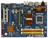
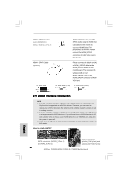
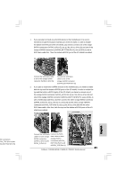
HDMI_SPDIF Header (3-pin HDMI_SPDIF1) (see p.2 No. 28 or p.3 No. 27) HDMI_SPDIF header, providing SPDIF audio output to HDMI VGA card, allows the system to con nect HDMI Digital TV/ projector/LCD devices. Please connect the HDMI_SPDIF connector of HDMI VGA card to this header. HDMI_SPDIF Cable (Optional) C B A Please connect the black end (A) of HDMI_SPDIF cable to the HDMI_SPDIF header on the motherboard. Then connect the white end (B or C) of HDMI_SPDIF cable to the HDMI_SPDIF connector of HDMI VGA card. A. black end B. white end (2-pin) C. white end (3-pin) 2.9 eSATAII Interface Introduction NOTE: 1. If you set "Configure SATAII as" option in BIOS setup to AHCI or RAID mode, Hot Plug function is supported with eSATAII devices. Therefore, you can insert or remove your eSATAII devices to the eSATAII ports while the system is power-on and in working condition. 2. If you set "Configure SATAII as" option in BIOS setup to IDE mode, Hot Plug function is not supported with eSATAII devices. If you still want to use eSATAII function in IDE mode, please insert or remove your eSATAII devices to the eSATAII ports only when the system is power-off. 3. Please refer to page 32 to 33 for detailed information of RAID mode, IDE mode, and AHCI mode. How to install eSATAII? English SATAII connectors (SATAII_5 (Port 4) and SATAII_6 (Port 5)) eSATAII connectors (eSATAII_TOP (Port 4) and eSATAII_BOTTOM (Port 5)) 30 ASRock P45XE-WiFiN / P45XE-R / P45XE Motherboard
-
 1
1 -
2
-
3
-
4
-
5
-
6
-
7
-
8
-
9
-
10
-
11
-
12
-
13
-
14
-
15
-
16
-
17
-
18
-
19
-
20
-
21
-
22
-
23
-
24
-
 25
25 -
 26
26 -
 27
27 -
 28
28 -
 29
29 -
 30
30 -
 31
31 -
 32
32 -
 33
33 -
 34
34 -
 35
35 -
36
-
37
-
38
-
39
-
40
-
41
-
42
-
43
-
44
-
45
-
46
-
47
-
48
-
49
-
50
-
51
-
52
-
53
-
54
-
55
-
56
-
57
-
58
-
59
-
60
-
61
-
62
-
63
-
64
-
65
-
66
-
67
-
68
-
69
-
70
-
71
-
72
-
73
-
74
-
75
-
76
-
77
-
78
-
79
-
80
-
81
-
82
-
83
-
84
-
85
-
86
-
87
-
88
-
89
-
90
-
91
-
92
-
93
-
94
-
95
-
96
-
97
-
98
-
99
-
100
-
101
-
102
-
103
-
104
-
105
-
106
-
107
-
108
-
109
-
110
-
111
-
112
-
113
-
114
-
115
-
116
-
117
-
118
-
119
-
120
-
121
-
122
-
123
-
124
-
125
-
126
-
127
-
128
-
129
-
130
-
131
-
132
-
133
-
134
-
135
-
136
-
137
-
138
-
139
-
140
-
141
-
142
-
143
-
144
-
145
-
146
-
147
-
148
-
149
-
150
-
151
-
152
-
153
-
154
-
155
-
156
-
157
-
158
-
159
-
160
-
161
-
162
-
163
-
164
-
165
-
166
-
167
-
168
-
169
-
170
-
171
-
172
-
173
-
174
-
175
-
176
-
177
-
178
-
179
-
180
-
181
-
182
-
183
-
184
-
185
-
186
-
187
-
188
-
189
-
190
-
191
-
192
-
193
-
194
 |
 |
