ASRock P45XE-R Quick Installation Guide - Page 31
If you plan to install two eSATAII devices to this motherboard, you need to enable
 |
View all ASRock P45XE-R manuals
Add to My Manuals
Save this manual to your list of manuals |
Page 31 highlights
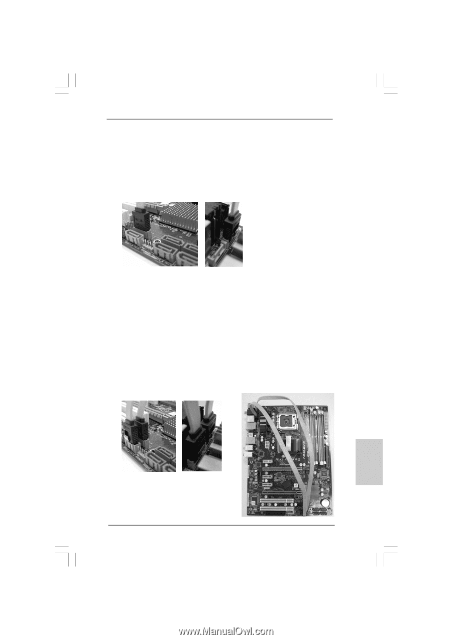
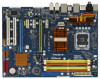
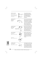
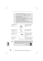
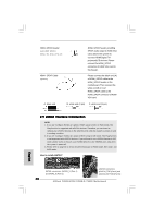
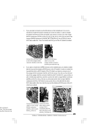
1. If you just plan to install one eSATAII device to this motherboard, it is recommended to enable the bottom eSATAII port of the I/O shield. In order to enable the bottom eSATAII port of the I/O shield, you need to connect one of the orage SATAII connectors (SATAII_6 (Port 5); see p.2 No.19 or p.3 No.18) and one of the orange eSATAII connectors (eSATAII_BOTTOM (Port 5); see p.2/3 No.1) with a SATA data cable first. Then the bottom eSATAII port of the I/O shield is enabled. Connect the SATA data cable to one of the orange SATAII connector (SATAII_6 (Port 5)) Connect the SATA data cable to one of the orange eSATAII connector (eSATAII_BOTTOM (Port 5)) 2. If you plan to install two eSATAII devices to this motherboard, you need to enable both the top and the bottom eSATAII ports of the I/O shield. In order to enable the top and the bottom eSATAII ports of the I/O shield, you have to connect one of the orange SATAII connector (SATAII_6 (Port 5); see p.2 No.19 or p.3 No.18) and one of the orange eSATAII connector (eSATAII_BOTTOM (Port 5); see p.2/3 No.1) with a SATA data cable first, and then connect the other orange SATAII connector (SATAII_5 (Port 4); see p.2 No.21 or p.3 No.20) and the other orange eSATAII connector (eSATAII_TOP (Port 4); see p.2 No.39 or p.3 No.38) with the other SATA data cable. After that, both the top and the bottom eSATAII ports of the I/O shield are enabled. English TAII connectors ATAII_TOP (Port 4) and TAII_BOTTOM (Port 5)) Connect the SATA data Connect the SATA cables to both orange data cables to both SATAII connectors orange eSATAII (SATAII_6 (Port 5) and connectors (eSATAII_ SATAII_5 (Port 4)) BOTTOM (Port 5) and eSATAII_TOP (Port 4)) 31 ASRock P45XE-WiFiN / P45XE-R / P45XE Motherboard
-
 1
1 -
2
-
3
-
4
-
5
-
6
-
7
-
8
-
9
-
10
-
11
-
12
-
13
-
14
-
15
-
16
-
17
-
18
-
19
-
20
-
21
-
22
-
23
-
24
-
25
-
 26
26 -
 27
27 -
 28
28 -
 29
29 -
 30
30 -
 31
31 -
 32
32 -
 33
33 -
 34
34 -
 35
35 -
 36
36 -
37
-
38
-
39
-
40
-
41
-
42
-
43
-
44
-
45
-
46
-
47
-
48
-
49
-
50
-
51
-
52
-
53
-
54
-
55
-
56
-
57
-
58
-
59
-
60
-
61
-
62
-
63
-
64
-
65
-
66
-
67
-
68
-
69
-
70
-
71
-
72
-
73
-
74
-
75
-
76
-
77
-
78
-
79
-
80
-
81
-
82
-
83
-
84
-
85
-
86
-
87
-
88
-
89
-
90
-
91
-
92
-
93
-
94
-
95
-
96
-
97
-
98
-
99
-
100
-
101
-
102
-
103
-
104
-
105
-
106
-
107
-
108
-
109
-
110
-
111
-
112
-
113
-
114
-
115
-
116
-
117
-
118
-
119
-
120
-
121
-
122
-
123
-
124
-
125
-
126
-
127
-
128
-
129
-
130
-
131
-
132
-
133
-
134
-
135
-
136
-
137
-
138
-
139
-
140
-
141
-
142
-
143
-
144
-
145
-
146
-
147
-
148
-
149
-
150
-
151
-
152
-
153
-
154
-
155
-
156
-
157
-
158
-
159
-
160
-
161
-
162
-
163
-
164
-
165
-
166
-
167
-
168
-
169
-
170
-
171
-
172
-
173
-
174
-
175
-
176
-
177
-
178
-
179
-
180
-
181
-
182
-
183
-
184
-
185
-
186
-
187
-
188
-
189
-
190
-
191
-
192
-
193
-
194
 |
 |