ASRock X79 Extreme11 User Manual
ASRock X79 Extreme11 Manual
 |
View all ASRock X79 Extreme11 manuals
Add to My Manuals
Save this manual to your list of manuals |
ASRock X79 Extreme11 manual content summary:
- ASRock X79 Extreme11 | User Manual - Page 1
X79 Extreme11 User Manual Version 1.0 Published April 2012 Copyright©2012 ASRock INC. All rights reserved. 1 - ASRock X79 Extreme11 | User Manual - Page 2
commitment by ASRock. ASRock assumes no responsibility for any errors or omissions that may appear in this manual. With respect to the contents of this manual, ASRock does not , USA ONLY The Lithium battery adopted on this motherboard contains Perchlorate, a toxic substance controlled in Perchlorate - ASRock X79 Extreme11 | User Manual - Page 3
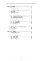
61 2.18 Hot Plug and Hot Swap Functions for SATA / SATA2 HDDs 62 2.19 Hot Plug and Hot Swap Functions for SATA3 HDDs...... 62 2.20 SATA / SATA2 / SATA3 HDD Hot Plug Feature and Operation Guide 63 2.21 Driver Installation Guide 65 2.22 Installing Windows® 7 / 7 64-bit / VistaTM / VistaTM 64 - ASRock X79 Extreme11 | User Manual - Page 4
73 3.3 OC Tweaker Screen 74 3.4 Advanced Screen 79 3.4.1 CPU Configuration 80 3.4.2 North Bridge Configuration 82 3.4.3 South Bridge Configuration 96 4 Software Support 97 4.1 Install Operating System 97 4.2 Support CD Information 97 4.2.1 Running Support CD 97 4.2.2 Drivers Menu 97 4.2.3 - ASRock X79 Extreme11 | User Manual - Page 5
model you are using. www.asrock.com/support/index.asp 1.1 Package Contents ASRock X79 Extreme11 Motherboard (CEB Form Factor: 12.0-in x 10.5-in, 30.5 cm x 26.7 cm) ASRock X79 Extreme11 Quick Installation Guide ASRock X79 Extreme11 Support CD 6 x Serial ATA (SATA) Data Cables (Optional) 2 x Serial - ASRock X79 Extreme11 | User Manual - Page 6
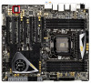
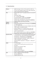
family for the LGA 2011 Socket - Digi Power Design - 24 + 2 Power Phase Design - Dual-Stack MOSFET (DSM) (see CAUTION 1) - Supports Intel® Turbo Boost 2.0 Technology - Supports Hyper-Threading Technology (see CAUTION 2) - Supports Untied Overclocking Technology - Intel® X79 - Quad Channel DDR3 - ASRock X79 Extreme11 | User Manual - Page 7
SATA3 6.0 Gb/s connectors by Intel® X79, support RAID (RAID 0, RAID 1, RAID 5, RAID 10 and Intel Rapid Storage 3.0), NCQ, AHCI CPU Fan connectors (1 x 4-pin, 1 x 3-pin) - 3 x Chassis Fan connectors (1 x 4-pin, 2 x 3-pin) - 1 x Power Fan connector (3-pin) - 1 x SB Fan connector (3-pin) - 24 pin ATX - ASRock X79 Extreme11 | User Manual - Page 8
- Supports jumperfree - SMBIOS 2.3.1 Support - CPU, VCCSA, DRAM, VTT, CPU PLL, PCH1.1V, PCH1.5V Voltage Multi-adjustment Support CD - Drivers, Utilities, AntiVirus Software (Trial Version), CyberLink MediaEspresso 6.5 Trial, ASRock MAGIX Multimedia Suite - OEM Unique Feature - ASRock Extreme - ASRock X79 Extreme11 | User Manual - Page 9
. 2. About the setting of "Hyper Threading Technology", please check page 80. 3. This motherboard supports Quad Channel Memory Technology. Before you implement Quad Channel Memory Technology, make sure to read the installation guide of memory modules on page 19 for proper installation. 4. Due to the - ASRock X79 Extreme11 | User Manual - Page 10
5. Currently Intel® Socket 2011 Sandy Bridge-E Processor doesn't support PCIE 3.0, but this motherboard is already PCIE 3.0 hardware ready. It depends on Intel's CPU to enable PCIE 3.0. Please check Intel's website for information on future CPU updates and releases. 6. For serious gamers and - ASRock X79 Extreme11 | User Manual - Page 11
Windows® OS 32-bit CPU. ASRock XFast RAM shortens the loading time of BIOS update process, ASRock Crashless BIOS will automatically finish the BIOS update procedure after regaining power. Please note that BIOS files need to be placed in the root directory of your USB disk. Only USB2.0 ports support - ASRock X79 Extreme11 | User Manual - Page 12
CPU. 20. While CPU overheat is detected, the system will automatically shutdown. Before you resume the system, please check if the CPU fan on the motherboard meet EuP standards, an EuP ready motherboard and an EuP ready power supply are required. According to Intel's suggestion, the EuP ready power - ASRock X79 Extreme11 | User Manual - Page 13
1 13 64Mb BIOS 14 Top: LINE IN Center: FRONT Bottom: MIC IN CHA_FAN3 CMOS 50 Battery 15 49 PCIE1 16 SATA3_0_1 X PCI Express 3.0 Ready Fast RAM SB_FAN1 17 48 PCIE2 PLX SATA2_0_1 LSI SAS 8747 Intel 18 SATA2_2_3 Super I/O PCIE3 X79 19 47 X79 Extreme11 SAS_0_1 46 PCIE4 - ASRock X79 Extreme11 | User Manual - Page 14
4 LAN RJ-45 Port 5 USB 3.0 Ports (USB3_23) 6 Central / Bass (Orange) 7 Rear Speaker (Black) 8 Optical SPDIF Out Port 9 Line In (Light Blue) ** 10 11 12 13 14 15 16 17 18 Front Speaker (Lime) Microphone (Pink) eSATA Connectors USB 3.0 Ports (USB3_0_1) USB 2.0 Ports (USB3_67) USB 2.0 Ports (USB3_4_5 - ASRock X79 Extreme11 | User Manual - Page 15
screws into the screw holes to secure the mother- board to the chassis, please do not over-tighten the screws! Doing so may damage the motherboard. Before you install or remove any component, ensure that the power is switched off or the power cord is detached from the power supply. Failure - ASRock X79 Extreme11 | User Manual - Page 16
For the installation of Intel 2011-Pin CPU, please follow the steps below. 2011-Pin Socket Overview Before you insert the 2011-Pin CPU into the socket, please check if the CPU surface is unclean or if there are any bent pins in the socket. Do not force to insert the CPU into the socket if - ASRock X79 Extreme11 | User Manual - Page 17
Verify that the CPU is within the socket and properly mated to the orient keys. Step 3. Close the socket: Step 3-1. Flip the load plate onto the IHS, then the cover will automatically come off by itself. The cover must be placed if returning the motherboard for after service. Step 3-2. Press down - ASRock X79 Extreme11 | User Manual - Page 18
Heatsink This motherboard is equipped with a 2011-Pin socket that supports Intel 2011Pin CPUs. Please adopt the type of heatsink and cooling fan compliant with Intel 2011-Pin CPU to dissipate heat. Before you install the heatsink, you need to spray thermal interface material between the CPU and the - ASRock X79 Extreme11 | User Manual - Page 19
slots, and supports Quad Channel Memory Technology. For quad channel configuration, you always need to install identical (the same brand, speed, size and chip-type) DDR3 DIMM in the slots, so that Quad Channel Memory Technology can be activated. 1. Due to Intel® CPU spec definition, please install - ASRock X79 Extreme11 | User Manual - Page 20
notch on the DIMM matches the break on the slot. The DIMM only fits in one correct orientation. It will cause permanent damage to the motherboard and the DIMM if you force the DIMM into the slot in incorrect orientation. Step 3. Firmly insert the DIMM into the slot until the retaining - ASRock X79 Extreme11 | User Manual - Page 21
better thermal environment. 6. Currently Intel® Socket 2011 Sandy Bridge-E Processors don't support PCIE 3.0, but this motherboard is already PCIE 3.0 hardware ready. It depends on Intel's CPU to enable PCIE 3.0. Please check Intel's website for information on future CPU updates and releases. 21 - ASRock X79 Extreme11 | User Manual - Page 22
of the expansion card and make necessary hardware settings for the card before you start the installation. Remove the system unit cover (if your motherboard is already installed in a chassis). Remove the bracket facing the slot that you intend to use. Keep the screws for later use. Align the - ASRock X79 Extreme11 | User Manual - Page 23
This section explains how to configure your ASRock Game Blaster. 2.7.1 THX TRUSTUDIO PRO THX TruStudio Pro Click the power button on the left to activate or deactivate. Surround Control the level of audio immersion in music, movies and games. Crystalizer Enhance music and movies to make - ASRock X79 Extreme11 | User Manual - Page 24
2.7.2 CRYSTALVOICE Select a recording device Mic Volume Control the level of mic volume. Mic Boost Control the level of mic boost. CrystalVoice Click the power button on the left to activate or deactivate. FX Morph your voice into different characters and accents. Smart Volume Be heard clearly - ASRock X79 Extreme11 | User Manual - Page 25
2.7.3 SCOUT MODE Scout Mode Enable or disable scout mode. This proprietary technology allows you to hear your enemies from further away, giving you a distinct tactical advantage in combat. Hot Key Configuration Configure hot keys to enable or disable scout mode. 25 - ASRock X79 Extreme11 | User Manual - Page 26
2.7.4 SPEAKERS/HEADPHONES Speakers / Headphones Configuration Select the device connected. Optional Speakers: Center Enable or disable center speaker. Subwoofer Enable or disable subwoofer. Rear pair Enable or disable rear pair speakers. If there are both speakers and front headphones connected, - ASRock X79 Extreme11 | User Manual - Page 27
2.7.5 MIXER Playback Speakers Control the level of speakers playback. SPDIF-Out Control the level of SPDIF-Out playback. Balance Control the level of various speaker's balance. REC Input Device Select input device. What U Hear Control the level of playback redirect. 27 - ASRock X79 Extreme11 | User Manual - Page 28
2.7.6 EQUALIZER EQ Choose from Flat, Acoustic, Classical, Country, Dance, Jazz, New Age, Pop, Rock and Vocal. 2.7.7 JACK SETUP 28 - ASRock X79 Extreme11 | User Manual - Page 29
Device Connected: Select the device connected. 5.1 Surround 7.1 EX Surround Stereo and Line-In Show Jack Setup dialog when an audio jack is inserted Enable or disable Jack Setup dialog. 29 - ASRock X79 Extreme11 | User Manual - Page 30
2.7.8 ADVANCED FEATURES Play stereo mix to digital output Enable or disable play stereo mix to digital output. 30 - ASRock X79 Extreme11 | User Manual - Page 31
2.7.9 PROFILE User Profiles You can save, load or delete your user profiles. The default is . 31 - ASRock X79 Extreme11 | User Manual - Page 32
Note 1. If you want to hear your own voice through the microphone (Playback mode). You can change your settings to "playback mode" by checking the "Listen to this device" box in Control panel Sound Recording Microphone Properties Listen. 2. If you want to change your playback device to a SPDIF-Out - ASRock X79 Extreme11 | User Manual - Page 33
3-Way SLITM, 4-Way SLITM and Quad SLITM Operation Guide This motherboard supports NVIDIA® SLITM, 3-Way SLITM, 4-Way SLITM and . 2. Make sure that your graphics card driver supports NVIDIA® SLITM technology (driver version 280.41 and later). Download the driver from NVIDIA website (www.nvidia.com). - ASRock X79 Extreme11 | User Manual - Page 34
power source to the PCI Express graphics cards. Step3. Align and insert the ASRock SLI_Bridge_3S Card to the goldfingers on each graphics card. Make sure the ASRock SLI_Bridge_3S Card is firmly in place. ASRock SLI_Bridge_3S Card Step4. Connect a VGA cable or a DVI cable to the monitor connector - ASRock X79 Extreme11 | User Manual - Page 35
connected. Repeat this step on the three graphics cards. Step3. Align and insert the ASRock 3-Way SLI Bridge Card to the goldfingers on each graphics card. Make sure the ASRock 3-Way SLI Bridge Card is firmly in place. ASRock 3-Way SLI Bridge Card Step4. Connect a VGA cable or a DVI cable to the - ASRock X79 Extreme11 | User Manual - Page 36
cards will not work together properly. (Even the GPU chips version shall be the same.) Each graphics card should have two goldfingers for the ASRock SLI Bridge Card connectors. Insert one graphics card into the PCIE1 slot, another graphics card into the PCIE3 slot, the third graphics card into - ASRock X79 Extreme11 | User Manual - Page 37
Installation and Setup Install the graphics card drivers to your system. After that, you can enable the MultiGraphics Processing Unit (GPU) feature in the NVIDIA® nView system tray utility. Please follow the below - ASRock X79 Extreme11 | User Manual - Page 38
G. Reboot your system. H. You can freely enjoy the benefits of SLITM or Quad SLITM. For Windows® VistaTM / VistaTM 64-bit / 7 / 7 64-bit OS: (For 3-Way SLITM or 4-Way SLITM mode) A. Follow steps A to E on page 37. B. In Select an SLI configuration item, please select Enable 3-way SLI or Enable 4-way - ASRock X79 Extreme11 | User Manual - Page 39
CrossFireXTM Operation Guide This motherboard supports CrossFireXTM, 3- are supported with Windows® VistaTM / 7 OS only. Please check AMD's website for CrossFireXTM driver updates. 1. released or will release in the future, please refer to AMD graphics card manuals for detailed installation guide - ASRock X79 Extreme11 | User Manual - Page 40
on the top of the Radeon graphics cards. (The CrossFire Bridge is provided with the graphics card you purchase, not bundled with this motherboard. Please refer to your graphics card vendor for details.) CrossFire Bridge Step 3. Connect the DVI monitor cable to the DVI connector on the - ASRock X79 Extreme11 | User Manual - Page 41
Radeon graphics cards on PCIE3 and PCIE5 slots. (The CrossFireTM Bridge is provided with the graphics card you purchase, not bundled with this motherboard. Please refer to your graphics card vendor for details.) CrossFireTM Bridge Step 3. Connect the DVI monitor cable to the DVI connector on the - ASRock X79 Extreme11 | User Manual - Page 42
graphics cards on PCIE5 and PCIE7 slots. (The CrossFireTM Bridge is provided with the graphics card you pur- chase, not bundled with this motherboard. Please refer to your graphics card vendor for details.) CrossFireTM Bridge Step 3. Connect the DVI monitor cable to the DVI connector on the - ASRock X79 Extreme11 | User Manual - Page 43
download. We recommend using this utility to uninstall any previously installed Catalyst drivers prior to installation. Please check AMD's website for AMD driver updates. Step 3. Step 4. Step 5. Install the required drivers to your system. For Windows® 7 / VistaTM OS: Install the CATALYST Control - ASRock X79 Extreme11 | User Manual - Page 44
please check AMD's website for updates and details. 2.10 Surround Display Feature This motherboard supports Surround Display upgrade. With the external add-on PCI Express VGA cards, you can easily enjoy the benefits of Surround Display feature. For detailed instructions, please refer to the document - ASRock X79 Extreme11 | User Manual - Page 45
2.11 ASRock Smart Remote Installation Guide ASRock Smart Remote is only used for ASRock motherboards with a CIR header. Please refer to the procedures below for the quick installation and usage of ASRock Smart Remote. Step1. Find the CIR header located next to the USB 2.0 header on your ASRock - ASRock X79 Extreme11 | User Manual - Page 46
most of the chassis on the market. 3. The Multi-Angle CIR Receiver does not support Hot-Plug. Please install it before you boot the system. * ASRock Smart Remote is only supported by some ASRock motherboards. Please refer to ASRock's website for the motherboard support list: http://www.asrock.com 46 - ASRock X79 Extreme11 | User Manual - Page 47
you need to clear the CMOS when you just finish updating the BIOS, you must boot up the system first, and then shut it down before you do the clear-CMOS action. Please be noted that the password, date, time, user default profile, 1394 GUID and MAC address will be cleared only if the - ASRock X79 Extreme11 | User Manual - Page 48
caps over the headers and connectors will cause permanent damage of the motherboard! Serial ATA2 Connectors (SATA2_0_1: see p.13, No. 18) support SAS/SATA data cables for internal storage devices. The current SAS/SATA3 interface allows up to 6.0 Gb/s data transfer rate. We recommend using Intel® X79 - ASRock X79 Extreme11 | User Manual - Page 49
of the SATA power cable to the power connector of the power supply. USB 2.0 Headers (9-pin USB_8_9) (see p.13, No. 26) (9-pin USB_10_11) (see p.13, No. 29) Besides eight default USB 2.0 ports on the I/O panel, there are three USB 2.0 headers on this motherboard. Each USB 2.0 header can support two - ASRock X79 Extreme11 | User Manual - Page 50
panel, there are two USB 3.0 headers on this motherboard. Each USB 3.0 header can support two USB 3.0 ports. Infrared Module Header (5-pin supports Jack Sensing, but the panel wire on the chassis must support HDA to function correctly. Please follow the instruction in our manual and chassis manual - ASRock X79 Extreme11 | User Manual - Page 51
C. Connect Ground (GND) to Ground (GND). D. MIC_RET and OUT_RET are for HD audio panel only. You don't need to connect them for AC'97 audio panel. E. To activate the front mic. For Windows® XP / XP 64-bit OS: Select "Mixer". Select "Recorder". Then click "FrontMic". For Windows® 7 / 7 64-bit / - ASRock X79 Extreme11 | User Manual - Page 52
pin CHA_FAN2) Control. SB_FAN1 supports (see p.13, No. 33) Quiet Fan. (3-pin CHA_FAN3) (see p.13, No. 15) (3-pin PWR_FAN1) (see p.13, No. 1) (3-pin SB_FAN1) (see p.13, No. 16) CPU Fan Connectors (4-pin CPU_FAN1) (see p.13, No. 7) Please connect the CPU fan cable to the connector - ASRock X79 Extreme11 | User Manual - Page 53
) support, the 3-Pin CPU fan still can work successfully even without the fan speed control function. If you plan to connect the 3-Pin CPU fan to the CPU fan connector on this motherboard, please connect it to Pin 1-3. Pin 1-3 Connected 3-Pin Fan Installation (3-pin CPU_FAN2) (see p.13, No. 8) ATX - ASRock X79 Extreme11 | User Manual - Page 54
, No. 40) Besides one default IEEE 1394 port on the I/O panel, there is one IEEE 1394 header (FRONT_1394) on this motherboard. This IEEE 1394 header can support one IEEE 1394 port. HDMI_SPDIF Header (2-pin HDMI_SPDIF1) (see p.13, No. 42 HDMI_SPDIF header provides SPDIF audio output to HDMI - ASRock X79 Extreme11 | User Manual - Page 55
chassis screws. Step 5 Plug the Front USB 3.0 cable into the USB 3.0 header (USB3_4_5 or USB3_6_7) on the motherboard. Step 6 The Front USB 3.0 Panel is ready to use. The Installation Guide of Rear USB 3.0 Bracket Step 1 Unscrew the two screws from the Front USB 3.0 Step 2 Put the USB 3.0 cable - ASRock X79 Extreme11 | User Manual - Page 56
2.14 Smart Switches The motherboard has three smart switches: power switch, reset switch and clear CMOS switch, allowing users to quickly turn on/off or reset the system to clear - ASRock X79 Extreme11 | User Manual - Page 57
, which makes troubleshooting even easier. error codes Microcode not found Microcode not loaded PEI Core is started Pre-memory CPU initialization is started Pre-memory CPU initialization (CPU module specific) Pre-memory CPU initialization (CPU module specific) Pre-memory CPU initialization (CPU - ASRock X79 Extreme11 | User Manual - Page 58
No usable memory detected Unspecified memory initialization error Memory not installed Invalid CPU type or Speed CPU mismatch CPU self test failed or possible CPU cache error CPU micro-code is not found or micro-code update is failed Internal CPU error reset PPI is not available Reserved for future - ASRock X79 Extreme11 | User Manual - Page 59
Services CPU DXE initialization is started CPU DXE initialization (CPU module specific) CPU DXE initialization (CPU module specific) CPU DXE initialization (CPU module specific) CPU DXE initialization (CPU Device Selection (BDS) phase is started Driver connecting is started PCI Bus initialization is - ASRock X79 Extreme11 | User Manual - Page 60
Services CPU initialization error North Bridge initialization error South Bridge initialization error Some of the Architectural Protocols are not available PCI resource allocation error Error loading Boot Option (LoadImage returned error) Boot Option is failed (StartImage returned error) Flash update - ASRock X79 Extreme11 | User Manual - Page 61
motherboard adopts Intel® X79 chipset that supports Serial ATA (SATA) / Serial ATA2 (SATA2) hard disks and RAID (RAID 0, RAID 1, RAID 5, RAID 10 and Intel Rapid Storage 3.0) functions. You may install SATA / SATA2 hard disks on this motherboard for internal storage devices. This section will guide - ASRock X79 Extreme11 | User Manual - Page 62
SATA / SATA2 HDDs This motherboard supports Hot Plug and Hot Swap for SATA / SATA2 in RAID / AHCI mode. Intel® X79 chipset provides hardware support for Advanced Host controller Interface (AHCI), a new programming interface for SATA HDDs while the system is still power-on and in working condition. 62 - ASRock X79 Extreme11 | User Manual - Page 63
be supported by the chipset because of its limitation. The SATA / SATA2 / SATA3 Hot Plug support information of our motherboards is indicated in the product spec on our website: www.asrock.com 2. Make sure your SATA / SATA2 / SATA3 HDD can support Hot Plug from your dealer or HDD user manual. SATA - ASRock X79 Extreme11 | User Manual - Page 64
Step 2 Connect the SATA data cable to the motherboard's SATA2 / SATA3 connector. SATA power cable 1x4-pin power connector (White) Step 3 Connect the SATA 15-pin power cable connector's (Black) end to the SATA / SATA2 / SATA3 HDD. Step 4 Connect the SATA data cable to the SATA / SATA2 / SATA3 HDD - ASRock X79 Extreme11 | User Manual - Page 65
listed on the support CD driver page. Please follow the order from top to bottom to install those required drivers. Therefore, the drivers you install can Installation Guide" and "Intel Rapid Storage Information" for RAID configuration. Please refer to the document in the Support CD, "Guide to SATA - ASRock X79 Extreme11 | User Manual - Page 66
/ 7 64-bit / VistaTM / VistaTM 64-bit OS on your system. Using SATA / SATA2 / SATA3 HDDs without NCQ function STEP 1: Set Up UEFI. A. Enter UEFI SETUP UTILITY Advanced screen Storage Configuration. B. Set the option "SATA Mode" to [IDE]. (For SATA2_0 to SATA2_3, SATA3_0 and SATA3_1 ports.) - ASRock X79 Extreme11 | User Manual - Page 67
This motherboard supports Untied Overclocking Technology, which means during overclocking, BCLK enjoys better margin due to fixed PCI / PCIE buses. Before you enable Untied Overclocking function, please enter "Overclock Mode" option of UEFI setup to set the selection from [Auto] to [Manual - ASRock X79 Extreme11 | User Manual - Page 68
25 Teaming Function Operation Guide Dual LAN with Teaming function enabled on this motherboard allows two single connections driver from the following path of motherboard Support CD: 32-bit: .. \Drivers\LAN\Broadcom\Teaming\IA32 64-bit: .. \Drivers\LAN\Broadcom\Teaming\x64 (This is a special driver - ASRock X79 Extreme11 | User Manual - Page 69
the team. The LSO, CO, and RSS properties are enabled for a team only when all of the members support and are configured for the feature. * Adding a network adapter to a team where its driver is disabled may negatively affect the offloading capabilities of the team. This may have an impact on the - ASRock X79 Extreme11 | User Manual - Page 70
the team information. 11. Repeat steps 5. a team name more than once, an error message is displayed indicating that the name already has been correctly performed, a virtual team adapter driver is created for each configured team. * If supported for testing, it is recommended to connect team members to - ASRock X79 Extreme11 | User Manual - Page 71
* Not all network adapters made by others are supported or fully certified for teaming. 14. Configure the team IP address. a. From Control Panel, double-click Network Connections. b. Right-click the name of the team - ASRock X79 Extreme11 | User Manual - Page 72
ASRock Interactive UEFI is a blend of system configuration tools, cool sound effects and stunning visuals. Not only will it make BIOS setup less difficult but also a lot more amusing. This section explains how to use the UEFI SETUP UTILITY to configure your system. The UEFI chip on the motherboard - ASRock X79 Extreme11 | User Manual - Page 73
3.1.2 Navigation Keys Please check the following table for the descriptions of each navigation key. Navigation Key(s) Function Description + / - To change option for the selected items Switch to next function Go to the previous page Go to the next page Go to - ASRock X79 Extreme11 | User Manual - Page 74
load CPU EZ overclocking settings. Please note that overclocking may cause damage to your CPU and motherboard. It should be done at your own risk and expense. CPU Configuration CPU Ratio Setting Use this item to change the ratio value of this motherboard. Intel SpeedStep Technology Intel SpeedStep - ASRock X79 Extreme11 | User Manual - Page 75
voltage when CPU is in Turbo mode. Additional Turbo Voltage Use this item to add voltage when CPU Frequency If [Auto] is selected, the motherboard will detect the memory module(s) inserted Manual setting. The default is [Auto]. DRAM tRCD Use this item to change RAS# to CAS# Delay (tRCD) Auto/Manual - ASRock X79 Extreme11 | User Manual - Page 76
setting. The default is [Auto]. DRAM tCWL Use this item to change CAS# Write Latency (tCWL) Auto/Manual setting. The default is [Auto]. Command Rate Use this item to change Command Rate Auto/Manual setting. The default is [Auto]. DRAM Power Down Mode Use this item to adjust DDR power down mode - ASRock X79 Extreme11 | User Manual - Page 77
you to configure Rank Interleaving. The default value is [Auto]. DRAM tCCD Use this item to change DRAM tCCD Auto/Manual setting. The default is [Auto]. DRAM tRWSR Use this item to change DRAM tRWSR Auto/Manual setting. The default is [Auto]. DRAM tWRDD Use this item to change DRAM tWRDD Auto - ASRock X79 Extreme11 | User Manual - Page 78
DRAM tRRDR Auto/Manual setting. The default is [Auto]. DRAM Fine Tuning - SP Use this item to configure DRAM Fine Tuning - SP. The default is [Auto]. DRAM Fine Tuning - SN Use this item to configure DRAM Fine Tuning - SN. The default is [Auto]. Voltage Configuration CPU Core Voltage Use this to - ASRock X79 Extreme11 | User Manual - Page 79
3.4 Advanced Screen In this section, you may set the configurations for the following items: CPU Configuration, North Bridge Configuration, South Bridge Configuration, Storage Configuration, Super IO Configuration, ACPI Configuration, USB Configuration and ME Subsystem. Setting wrong values in this - ASRock X79 Extreme11 | User Manual - Page 80
3.4.1 CPU Configuration CPU Ratio Setting Use this item to change the ratio value of this motherboard. Intel Hyper Threading Technology To enable this feature, a computer system with an Intel processor that supports Hyper-Threading technology and an operating system that includes optimization for - ASRock X79 Extreme11 | User Manual - Page 81
through the native processor instructions HLT and MWAIT and requires no hardware support from the chipset. In the C1 power state, the processor maintains the context of the system caches. CPU C3 State Support Use this to enable or disable CPU C3 report to OS. CPU C6 State Support Use this to enable - ASRock X79 Extreme11 | User Manual - Page 82
Speed. The default value is [GEN2]. PCIE 4 & PCIE 5 & PCIE 6 & PCIE 7 Link Speed This allows you to select PCIE 4&5&6&7 Link Speed. The default value is [GEN2]. Intel(R) VT for Directed I/O Configuration Intel(R) VT-d Use this item to enable/disable - ASRock X79 Extreme11 | User Manual - Page 83
up when the power recovers. Deep Sx Mobile platforms support Deep S4/S5 in DC only and desktop platforms support Deep S4/S5 in AC only. Configuration options: [Disabled option to [Enabled] if you plan to use this motherboard to submit Windows® VistaTM certification. Good Night LED Use this item to enable - ASRock X79 Extreme11 | User Manual - Page 84
Onboard Debug Port LED Use this item to enable or disable Onboard Debug Port LED. 84 - ASRock X79 Extreme11 | User Manual - Page 85
[IDE Mode], [AHCI Mode], [RAID Mode] and [Disabled]. The default value is [AHCI Mode]. AHCI (Advanced Host Controller Interface) supports NCQ and other new features that will improve SATA disk performance but IDE mode does not have these advantages. Aggressive Link Power Management Use this item to - ASRock X79 Extreme11 | User Manual - Page 86
Marvell SATA3 controller as Boot Device. We recommend to use Intel® X79 SATA ports (SATA3_0, SATA3_1 and SATA2_0 to SATA2_3) for your bootable devices. This will minimum your boot time and get the best performance. But if you - ASRock X79 Extreme11 | User Manual - Page 87
3.4.5 Super IO Configuration Serial Port Use this item to enable or disable the onboard serial port. Serial Port Address Use this item to set the address for the onboard serial port. Configuration options: [3F8h / IRQ4] and [3E8h / IRQ4]. Infrared Port Use this item to enable or disable the onboard - ASRock X79 Extreme11 | User Manual - Page 88
3.4.6 ACPI Configuration Suspend to RAM Use this item to select whether to auto-detect or disable the Suspend-toRAM feature. Select [Auto] will enable this feature if the OS supports it. Check Ready Bit Use this item to enable or disable the feature Check Ready Bit. PS/2 Keyboard Power On Use this - ASRock X79 Extreme11 | User Manual - Page 89
use of USB 2.0 controller. USB 3.0 Controller Use this item to enable or disable the use of USB 3.0 controller. Legacy USB Support Use this option to select legacy support for USB devices. There are four configuration options: [Enabled], [Auto], [Disabled] and [UEFI Setup Only]. The default value is - ASRock X79 Extreme11 | User Manual - Page 90
3.4.8 ME Subsystem Intel ME Subsystem Configuration ME Version 90 - ASRock X79 Extreme11 | User Manual - Page 91
or Windows®. Just save the new UEFI file to your USB flash drive, floppy disk or hard drive and launch this tool, then you can update your UEFI only in a few clicks without preparing an additional floppy diskette or other complicated flash utility. Please be noted that the USB flash drive - ASRock X79 Extreme11 | User Manual - Page 92
this function. Easy RAID Installer Easy RAID Installer can help you to copy the RAID driver from a support CD to your USB storage device. After copying the RAID driver to your USB storage device, please change "SATA Mode Selection" to "RAID", then you can start installing the OS in RAID mode. User - ASRock X79 Extreme11 | User Manual - Page 93
CPU temperature, motherboard temperature, CPU fan speed, chassis fan speed, and the critical voltage. CPU Fan 1 & 2 Setting This allows you to set CPU Target SB Temperature This allows you to set the target temperature to activate ASRock X-FAN. The default value is [50oC/122oF]. Target Fan Speed This - ASRock X79 Extreme11 | User Manual - Page 94
3.7 Boot Screen In this section, it will display the available devices on your system for you to configure the boot settings and the boot priority. Setup Prompt Timeout This shows the number of seconds to wait for setup activation key. 65535(0XFFFF) means indefinite waiting. Bootup Num-Lock If this - ASRock X79 Extreme11 | User Manual - Page 95
3.8 Security Screen In this section, you may set or change the supervisor/user password for the system. For the user password, you may also clear it. 95 - ASRock X79 Extreme11 | User Manual - Page 96
3.9 Exit Screen Save Changes and Exit When you select this option, the following message "Save configuration changes and exit setup?" will pop-out. Select [Yes] to save the changes and exit the UEFI SETUP UTILITY. Discard Changes and Exit When you select this option, the following message "Discard - ASRock X79 Extreme11 | User Manual - Page 97
install the necessary drivers to activate the devices. 4.2.3 Utilities Menu The Utilities Menu shows the application softwares that the motherboard supports. Click on a specific item then follow the installation wizard to install it. 4.2.4 Contact Information If you need to contact ASRock or want to - ASRock X79 Extreme11 | User Manual - Page 98
HDD Larger Than 2TB in AHCI Mode This motherboard adopts UEFI BIOS that allows Windows® OS to be installed on or at system POST. Set AHCI Mode in UEFI Setup Utility > Advanced > Storage Configuration > SATA Mode. 3. Choose the item "UEFI:xxx" to boot in UEFI Setup Utility > Boot > Boot - ASRock X79 Extreme11 | User Manual - Page 99
a HDD Larger Than 2TB in RAID Mode This motherboard adopts UEFI BIOS that allows Windows® OS to be installed on Copy Intel® RAID drivers into a USB flash disk. You can download the driver from ASRock's website and unzip the file into a USB flash disk OR copy the file from ASRock motherboard support - ASRock X79 Extreme11 | User Manual - Page 100
Windows® Installation Guide to install OS. If you install Windows® 7 64-bit / VistaTM 64-bit on a large hard disk (ex. Disk volume > 2TB), it may take more time to boot into Windows® or install driver/utilities. If you encounter this problem, you will need to follow the instructions below to fix - ASRock X79 Extreme11 | User Manual - Page 101
B. Disable "Volume Shadow Copy" service. a. Type "computer management" in the Start Menu, then press "Enter". b. Go to "Services and Applications>Services"; Then double click "Volume Shadow Copy". 101 - ASRock X79 Extreme11 | User Manual - Page 102
Disable" then Click "OK". C. Reboot your system. D. After reboot, please start to install motherboard drivers and utilities. Windows® 7 64-bit: A. Please request the hotfix KB2505454 through this link: http://support.microsoft.com/kb/2505454/ B. After installing Windows® 7 64-bit, install the hotfix
-
 1
1 -
 2
2 -
 3
3 -
 4
4 -
 5
5 -
 6
6 -
 7
7 -
8
-
9
-
10
-
11
-
12
-
13
-
14
-
15
-
16
-
17
-
18
-
19
-
20
-
21
-
22
-
23
-
24
-
25
-
26
-
27
-
28
-
29
-
30
-
31
-
32
-
33
-
34
-
35
-
36
-
37
-
38
-
39
-
40
-
41
-
42
-
43
-
44
-
45
-
46
-
47
-
48
-
49
-
50
-
51
-
52
-
53
-
54
-
55
-
56
-
57
-
58
-
59
-
60
-
61
-
62
-
63
-
64
-
65
-
66
-
67
-
68
-
69
-
70
-
71
-
72
-
73
-
74
-
75
-
76
-
77
-
78
-
79
-
80
-
81
-
82
-
83
-
84
-
85
-
86
-
87
-
88
-
89
-
90
-
91
-
92
-
93
-
94
-
95
-
96
-
97
-
98
-
99
-
100
-
101
-
102
 |
 |

1
X79 Extreme11
User Manual
Version 1.0
Published April 2012
Copyright©2012 ASRock INC. All rights reserved.