ASRock X79 Extreme11 User Manual - Page 13
Motherboard Layout - intel x79 chipset
 |
View all ASRock X79 Extreme11 manuals
Add to My Manuals
Save this manual to your list of manuals |
Page 13 highlights
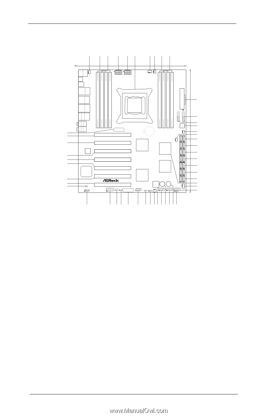
1.3 Motherboard Layout 1 2 3 4 5 6 78 9 10 26.7cm (10.5 in) 30.5cm (12.0 in) PS2 Keyboard USB 2.0 T: USB0 B: USB1 PWR_FAN1 Clr CMOS USB 2.0 T: USB2 B: USB3 USB 2.0 T: USB4 B: USB5 Top: RJ-45 ATX12V2 ATX12V1 Designed in Taipei CPU_FAN1 CPU_FAN2 ATXPWR1 DDR3 2400+ 4 Channels DDR3 DDR3_D2 (64 bit, 240-pin module) DDR3_D1 (64 bit, 240-pin module) DDR3_C2 (64 bit, 240-pin module) DDR3_C1 (64 bit, 240-pin module) USB3_6_7 DDR3_A1 (64 bit, 240-pin module) DDR3_A2 (64 bit, 240-pin module) DDR3_B1 (64 bit, 240-pin module) DDR3_B2 (64 bit, 240-pin module) IEEE 1394 USB 2.0 T: USB6 11 B: USB7 USB 3.0 T: USB0 B: USB1 Top: RJ-45 USB 3.0 T: USB2 B: USB3 RoHS 12 USB3_4_5 eSATA eSATA Top: Central/Bass Center: REAR SPK Bottom: Optical SPDIF SLI/XFIRE_PWR1 1 1 13 64Mb BIOS 14 Top: LINE IN Center: FRONT Bottom: MIC IN CHA_FAN3 CMOS 50 Battery 15 49 PCIE1 16 SATA3_0_1 X PCI Express 3.0 Ready Fast RAM SB_FAN1 17 48 PCIE2 PLX SATA2_0_1 LSI SAS 8747 Intel 18 SATA2_2_3 Super I/O PCIE3 X79 19 47 X79 Extreme11 SAS_0_1 46 PCIE4 20 2 oz Copper PCB SAS_2_3 45 Front USB 3.0 LSI 21 Sound CORE3D PCIE5 4-Way SLI PLX 2308 SAS_4_5 22 PCIE6 8747 44 23 SAS_6_7 43 42 HDMI_SPDIF1 1 HD_AUDIO1 1 PCIE7 FRONT_1394 IR1 CLRCMOS1 1 1 3 SLI/XFIRE_PWR2 PANEL1 PLED PWRBTN 1 HDLED RESET Dr. PWRBTN1 Debug USB_12_13 CHA_FAN2 PLED1 SPEAKER1 1 1 1 RSTBTN1 USB_10_11 1 USB_8_9 CHA_FAN1 1 1 CIR1 24 25 26 41 40 39 38 37 36 35 34 33 32 31 30 29 28 27 1 Power Fan Connector (PWR_FAN1) 2 2 x 240-pin DDR3 DIMM Slots (DDR3_A1, DDR3_B1, Black) 3 2 x 240-pin DDR3 DIMM Slots (DDR3_A2, DDR3_B2, Black) 4 ATX 12V Power Connector (ATX12V2) 5 ATX 12V Power Connector (ATX12V1) 6 2011-Pin CPU Socket 7 CPU Fan Connector (CPU_FAN1) 8 CPU Fan Connector (CPU_FAN2) 9 2 x 240-pin DDR3 DIMM Slots (DDR3_D2, DDR3_C2, Black) 10 2 x 240-pin DDR3 DIMM Slots (DDR3_D1, DDR3_C1, Black) 11 ATX Power Connector (ATXPWR1) 12 USB 3.0 Header (USB3_4_5, Black) 13 USB 3.0 Header (USB3_6_7, Black) 14 SPI Flash Memory (64Mb) 15 Chassis Fan Connector (CHA_FAN3) 16 SB Fan Connector (SB_FAN1) 17 SATA3 Connector (SATA3_0_1, Gray) 18 SATA2 Connector (SATA2_0_1, Black) 19 SATA2 Connector (SATA2_2_3, Black) 20 SAS Connector (SAS_0_1, Gray) 21 SAS Connector (SAS_2_3, Gray) 22 SAS Connector (SAS_4_5, Gray) 23 SAS Connector (SAS_6_7, Gray) 24 Intel X79 Chipset 25 Chassis Fan Connector (CHA_FAN1) 26 USB 2.0 Header (USB_8_9, Black) 27 Consumer Infrared Module Header (CIR1, Gray) 28 Reset Switch (RSTBTN1) 29 USB 2.0 Header (USB_10_11, Black) 30 Power Switch (PWRBTN1) 31 USB 2.0 Header (USB_12_13, Black) 32 Dr. Debug 33 Chassis Fan Connector (CHA_FAN2) 34 Chassis Speaker Header (SPEAKER1) 35 Power LED Header (PLED1) 36 System Panel Header (PANEL1, Black) 37 SLI / XFIRE Power Connector (SLI/XFIRE_PWR2) 38 Clear CMOS Jumper (CLRCMOS1) 39 Infrared Module Header (IR1) 40 Front Panel IEEE 1394 Header (FRONT_1394) 41 Front Panel Audio Header (HD_AUDIO1) 42 HDMI_SPDIF Header (HDMI_SPDIF1) 43 PCI Express 3.0 x16 Slot (PCIE7, Black) 44 PCI Express 3.0 x16 Slot (PCIE6, Black) 45 PCI Express 3.0 x16 Slot (PCIE5, Black) 46 PCI Express 3.0 x16 Slot (PCIE4, Black) 47 PCI Express 3.0 x16 Slot (PCIE3, Black) 48 PCI Express 3.0 x16 Slot (PCIE2, Black) 49 PCI Express 3.0 x16 Slot (PCIE1, Black) 50 SLI / XFIRE Power Connector (SLI/XFIRE_PWR1) 13
-
 1
1 -
2
-
3
-
4
-
5
-
6
-
7
-
 8
8 -
 9
9 -
 10
10 -
 11
11 -
 12
12 -
 13
13 -
 14
14 -
 15
15 -
 16
16 -
 17
17 -
 18
18 -
19
-
20
-
21
-
22
-
23
-
24
-
25
-
26
-
27
-
28
-
29
-
30
-
31
-
32
-
33
-
34
-
35
-
36
-
37
-
38
-
39
-
40
-
41
-
42
-
43
-
44
-
45
-
46
-
47
-
48
-
49
-
50
-
51
-
52
-
53
-
54
-
55
-
56
-
57
-
58
-
59
-
60
-
61
-
62
-
63
-
64
-
65
-
66
-
67
-
68
-
69
-
70
-
71
-
72
-
73
-
74
-
75
-
76
-
77
-
78
-
79
-
80
-
81
-
82
-
83
-
84
-
85
-
86
-
87
-
88
-
89
-
90
-
91
-
92
-
93
-
94
-
95
-
96
-
97
-
98
-
99
-
100
-
101
-
102
 |
 |