Acer AR380 F1 User Manual
Acer AR380 F1 Manual
 |
View all Acer AR380 F1 manuals
Add to My Manuals
Save this manual to your list of manuals |
Acer AR380 F1 manual content summary:
- Acer AR380 F1 | User Manual - Page 1
AR380 F1 Series User Guide - Acer AR380 F1 | User Manual - Page 2
Copyright © 2010. All Rights Reserved. Acer AR380 F1 Series User Guide Acer AR380 F1 Model Number : Serial Number: Purchase Date: Place of Purchase: - Acer AR380 F1 | User Manual - Page 3
iii Information for your safety and comfort Safety instructions Read these instructions carefully. Keep this document for future reference. Follow all warnings and instructions marked on the product. Turning the product off before cleaning Unplug this product from the wall outlet before cleaning. Do - Acer AR380 F1 | User Manual - Page 4
. • Never push objects of any kind into this product through cabinet slots as they may touch dangerous voltage points or short-out parts that could result in a fire or electric shock. Never spill liquid of any kind onto or into the product. • To avoid damage of internal components and to prevent - Acer AR380 F1 | User Manual - Page 5
in performance, indicating a need for service • the product does not operate normally after following the operating instructions Note: Adjust only those controls that are covered by the operating instructions, since improper adjustment of other controls may result in damage and will often require - Acer AR380 F1 | User Manual - Page 6
of the reach of small children. Disposal instructions Do not throw this electronic device into the (WEEE) regulations, visit http://www.acer-group.com/public/Sustainability/sustainability01.htm Industries Alliance at www.eiae.org. For lamp-specific disposal information, check www.lamprecycle.org. Tips - Acer AR380 F1 | User Manual - Page 7
vii • pain, swelling or throbbing • stiffness or tightness • coldness or weakness If you have these symptoms, or any other recurring or persistent discomfort and/or pain related to computer use, consult a physician immediately and inform your company's health and safety department. The following - Acer AR380 F1 | User Manual - Page 8
viii • Blink frequently to keep your eyes from drying out. Display • Keep your display clean. • Keep your head at a higher level than the top edge of the display so your eyes point downward when looking at the middle of the display. • Adjust the display brightness and/or contrast to a comfortable - Acer AR380 F1 | User Manual - Page 9
radio frequency energy and, if not installed and used in accordance with the instructions, may cause harmful interference to radio communications. However, there is no guarantee this equipment. Operation with non-certified peripherals is likely to result in interference to radio and TV reception. - Acer AR380 F1 | User Manual - Page 10
item of Telepermitted equipment of a different make or model, nor does it imply that any product is compatible with all of Telecom's network services. 2 This equipment is not capable, under all operating conditions, of correct operation at the higher speeds for which it is designed. Telecom will - Acer AR380 F1 | User Manual - Page 11
Specifications: a There shall be no more than 10 call attempts to the same number within any 30 minute period for any single manual that Telecom lines will always continue to support pulse dialing. 7 Use of pulse Should such problems occur, the user should NOT contact the telecom Fault Service. 8 This - Acer AR380 F1 | User Manual - Page 12
xii Notice: BSMI Power Supply Unit (PSU) statement Power supply unit (PSU) redundancy claim ensures that the system may continue to run normally in the event one power supply unit becomes inoperable. Under normal operation, both power supplies share the system loading. Laser compliance statement The - Acer AR380 F1 | User Manual - Page 13
Laserproduct klasse 1 Voorzichtig: Onzichtbare laserstraling indien geopend. Voorkom blootstelling aan straal. Declaration of Conformity for EU countries Hereby, Acer, declares that this system is in compliance with the essential requirements and other relevant provisions of Directive 1999/ 5/EC - Acer AR380 F1 | User Manual - Page 14
xiv - Acer AR380 F1 | User Manual - Page 15
the system: 20 Power-on problems 20 Configuring the system OS 22 Turning off the system 23 3 System upgrades 25 Installation precautions 26 ESD precautions 26 Pre-installation instructions 26 Post-installation instructions 27 Opening the server 28 Configuring the storage devices - Acer AR380 F1 | User Manual - Page 16
Logging Boot Settings Boot Device Priority Hard Disk Drives CD/DVD Drive Exit 5 System troubleshooting Resetting the system Initial system startup problems BIOS error beep codes Initial troubleshooting checklist Hardware diagnostic testing Checking the boot-up status Verifying the condition of the - Acer AR380 F1 | User Manual - Page 17
operating system 116 Specific problems and corrective actions 117 Appendix A: Server management tools Server management overview RAID Acer Smart Console Using Acer Smart Console Software requirements Accessing Acer Smart Console Acer Smart Console user interface System Information Server Health - Acer AR380 F1 | User Manual - Page 18
xviii - Acer AR380 F1 | User Manual - Page 19
1 System tour - Acer AR380 F1 | User Manual - Page 20
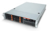
2 1 System tour Overview The AR380 F1 is a high-performance 2U rack-mount dual-socket server that supports up to two new generations of Intel architecture processors (Intel® Xeon 5500 series and Intel® Xeon 5600 series processors), DDR3 memory technology, PCI Express Gen2 (5.0Gb/s) quad onboard - Acer AR380 F1 | User Manual - Page 21
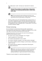
3 External and internal structure Front panel The illustration below shows the system front panel. With 3.5-inch HDD bays With 2.5-inch HDD bays - Acer AR380 F1 | User Manual - Page 22
4 1 System tour No. Icon 1 2 Component Optical drive Monitor port 3 USB 2.0 ports 4 LAN4 activity indicator 5 LAN3 activity indicator 6 System ID indicator/button 7 LAN2 activity indicator 8 LAN1 activity indicator 9 Status/fault indicator 10 HDD activity indicator 11 Power - Acer AR380 F1 | User Manual - Page 23
5 No. Icon 16 Component Hot-plug HDD activity indicator 17 Hot-plug HDD status indicator Front panel LED indicator status LED indicator LED color LED state Power indicator Green Green On Blinking (1 Hz at 50% duty cycle) N/A Off N/A Off HDD activity indicator Amber N/A Blinking Off - Acer AR380 F1 | User Manual - Page 24
6 LED indicator LAN activity indicators (LAN1, LAN2 LAN3 LAN4) LED color LED state Green On Green Blinking N/A Off 1 System tour Status LAN Link / No Access LAN Access Disconnect / Idle - Acer AR380 F1 | User Manual - Page 25
7 Rear panel No. 1 2 3 4 5 6 7 8-11 12 13 -14 15 16-18 19 Component Power supply modules PS/2 mouse port PS/2 keyboard port Server management port (RJ-45) (10/100 Mbps) USB 2.0 ports COM port Monitor port Gigabit LAN1 - 4 ports (10/100/1000 Mbps) Flex I/O expansion slot Full-height - Acer AR380 F1 | User Manual - Page 26
8 1 System tour Rear panel LED indicator status LED indicator System ID LED LED color LED state N/A Off Blue On Blue Blinking Status Normal System ID button pressed IPMI-activated system ID LAN port LED indicators LED indicator RJ45 LED (Left) RJ45 LED (Right) LED color N/A Green Amber - Acer AR380 F1 | User Manual - Page 27
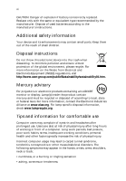
9 Internal components No. Component 1 Hard disk drive bay 2 System fan modules 3 Memory modules 4 Air duct 5 PCI riser board bracket assembly 6 Mainboard 7 Power supply module - Acer AR380 F1 | User Manual - Page 28
10 1 System tour Mainboard The mainboard becomes accessible once you open the system. It should look like the figure shown below. - Acer AR380 F1 | User Manual - Page 29
11 No. Connector Description 1 P1-DIMM3A DDR3 sockets for processor 1 P1-DIMM3B P1-DIMM3C P1-DIMM2A P1-DIMM2B P1-DIMM2C P1-DIMM1A P1-DIMM1B P1-DIMM1C 2 CPU2 Processor 2 socket 3 JPW1 ATX 24-pin power connector 4 JPW2/JPW3 12V 8-pin power connectors 5 FAN1 Chassis fan 1 6 - Acer AR380 F1 | User Manual - Page 30
12 1 System tour No. Connector 17 USB 4/5 18 JL1 19 USB 6 20 JTPM 21 COM2 22 SXB3 23 SXB1 24 SXB2 25 UIOP 26 ID 27 LAN3/LAN4 28 LAN1/LAN2 29 VGA1 30 VGA2 31 COM1 32 IPMI LAN 33 USB 0/1 34 KB/MS 35 SP1 36 JBT1 37 FAN7 38 FAN8 39 CPU1 Description Front panel accessible USB headers (USB4/5) Chassis - Acer AR380 F1 | User Manual - Page 31
13 No. Connector Description 40 P2-DIMM1C DDR3 sockets for processor 2 P2-DIMM1B P2-DIMM1A P2-DIMM2C P2-DIMM2B P2-DIMM2A P2-DIMM3C P2-DIMM3B P2-DIMM3A 41 USB7 Front panel accessible USB headers (USB7) - Acer AR380 F1 | User Manual - Page 32
14 Mainboard jumper settings 1 System tour No. Jumper Description 1 JBT1 Clear CMOS 2 JI2C1/ SMB to PCI-E slots JI2C2 3 JP3 ME Mode Select 4 JP5 ME Recovery Default Setting Instead of pins, this jumper consists of contact pads to prevent accidental clearing of the CMOS contents. To - Acer AR380 F1 | User Manual - Page 33
15 No. Jumper Description 5 JPB BMC Enabled 6 JPG1 VGA Enable 7 JPL1/ GLAN1/GLAN2 JPL2 Enable 8 JPRST1 BMC/PHY Enable 9 JWD Watch Dog Default Setting Pins 1~2 (enable) Pins 1~2 (enable) Pins 1~2 (enable) Pins 1~2 (enable) Pins 1~2 (reset) Note: Jumpers not indicated are for test - Acer AR380 F1 | User Manual - Page 34
16 Mainboard LEDs 1 System tour No. LED 1 D20 2 LE1 3 LE11 Description BMC heartbeat LED Standby power LED System ID LED State Green blinking Solid green Solid blue Status Normal Power on System ID - Acer AR380 F1 | User Manual - Page 35
2 System setup - Acer AR380 F1 | User Manual - Page 36
produced by electrical devices such as air conditioners, radio and TV transmitters, etc. Package contents Ensure you have the following items: • Acer AR380 system • Acer AR380 accessory box If any of the above items is damaged or missing, contact your dealer immediately. Save the boxes and packing - Acer AR380 F1 | User Manual - Page 37
the system to an incorrect voltage source. Refer to the illustration below for specific connection instructions on the peripherals you want to connect to the system. Front connections Rear connections Note: Consult the operating system manual for information on how to configure the network setup. - Acer AR380 F1 | User Manual - Page 38
starts up and displays a welcome message on the monitor. After that, a series of POST messages appears. The POST messages indicate if the system is running Lock, and Scroll Lock indicators on the keyboard light up. Power-on problems If the system does not boot after you have applied power, check - Acer AR380 F1 | User Manual - Page 39
21 Have an electrician check your power outlet. • Loose or improperly connected internal power cables. Check the internal cable connections. If you are not confident to perform this step, ask a qualified technician to assist you. Warning! Make sure all power cords are disconnected from the - Acer AR380 F1 | User Manual - Page 40
system. Note: To purchase the Acer Smart Server Manager software, contact your local Acer representative. To start using Smart Setup to close the disc tray. 6 On the Acer Smart Setup window, select OS Installation. 7 Follow all onscreen instructions. For more information, refer to the Smart - Acer AR380 F1 | User Manual - Page 41
Turning off the system There are two ways to turn off the server - via software or via hardware. The software procedure below applies turn off the system via hardware: If you cannot shut down the server using the software, press and hold the power button for at least four seconds. Quickly pressing the - Acer AR380 F1 | User Manual - Page 42
24 2 System setup - Acer AR380 F1 | User Manual - Page 43
3 System upgrades - Acer AR380 F1 | User Manual - Page 44
and foam packing. Pre-installation instructions Perform the steps below before you open the server or before you remove or server before you start installing components may cause serious damage. Do not attempt the procedures described in the following sections unless you are a qualified service - Acer AR380 F1 | User Manual - Page 45
a flat, stable surface. 5 Open the system according to the instructions on page 43. 6 Follow the ESD precautions described in this section when handling a server component. Post-installation instructions Perform the steps below after installing a server component. 1 See to it that all components are - Acer AR380 F1 | User Manual - Page 46
you proceed, make sure that you have turned off the system and all peripherals connected to it. Read the "Preinstallation instructions" on page 26. You need to open the server before you can install additional components or access the system's internal components. Refer to the following sections for - Acer AR380 F1 | User Manual - Page 47
29 2 Install the top cover. (1) Place the top cover on the chassis so that the tabs on the cover align with the slots on the chassis. (2) Slide the top cover toward the front of the chassis until it is fully closed. - Acer AR380 F1 | User Manual - Page 48
server. Accessing the drive bays Since SAS/SATA drives have hot-plug capability, you do not need to access the inside of the chassis or power down the system to install or replace SAS/SATA drives. Proceed to the next step for instructions. Note: The operating system you use must have RAID support - Acer AR380 F1 | User Manual - Page 49
31 order: Determining drive status Each HDD carrier features two status LED indicators (see page 5) to display the hard drive status. If you are replacing a failed HDD, determine which drive has failed by checking the hot-plug HDD status indicators. 3.5" HDD 2.5" HDD Description Onboard SATA RAID - Acer AR380 F1 | User Manual - Page 50
32 3 System upgrades Description HDD access RAID add-on card HDD present no access HDD access HDD failure HDD removal HDD insertion and rebuilding HDD locate Blink SAS: On SATA: Off Blink Off Off On Off Blink 1Hz Blink 4Hz Removing and installing a 3.5" hard disk drive Removing a 3.5" hard - Acer AR380 F1 | User Manual - Page 51
33 (3) Pull the lever and slide the carrier from the chassis. 4 Observe the post-installation instructions described on page 27. Installing a 3.5" hard disk drive with carrier 1 Slide the HDD carrier all the way into the drive bay. 2 Use the lever to - Acer AR380 F1 | User Manual - Page 52
34 3 Lock the HDD carrier. 3 System upgrades 4 Observe the post-installation instructions described on page 27. Removing and installing a 2.5" hard disk drive Removing a 2.5" hard disk drive with carrier 1 Observe the ESD precautions described on page 26. 2 Remove - Acer AR380 F1 | User Manual - Page 53
35 (4) Grasp the lever and pull the carrier from the chassis. 4 Observe the post-installation instructions described on page 27. Installing a 2.5" hard disk drive with carrier 1 Slide the HDD carrier all the way into the drive bay. 2 Use the lever to - Acer AR380 F1 | User Manual - Page 54
described on page 27 Removing the 2.5" Carrier Cage 1 Observe the ESD precautions described on page 26. 2 Observe the Pre-installation instructions on page 26. 3 Unplug the power and data cables from the cage drives. 4 Remove the four screws of the HDD cage (1). 5 Slide the HDD cage - Acer AR380 F1 | User Manual - Page 55
of the carrier hard drives. 4 Install the top cover. See page 28. 5 Observe the post-installation instructions described on page 27. Removing and installing an optical drive The system supports a slim SATA optical drive. Removing an optical drive 1 Observe the ESD precautions described on page 26 - Acer AR380 F1 | User Manual - Page 56
38 3 System upgrades 5 Pull the tab away from the drive and push the drive out of the system.(3) 6 Remove the ODD carrier frame. - Acer AR380 F1 | User Manual - Page 57
39 Installing an optical drive 1 Remove the ODD slot cover if present. 2 Install the ODD carrier frame to the ODD with the four screws. - Acer AR380 F1 | User Manual - Page 58
you hear a click and the locking tab locks into place (1). 4 Plug the power and data cables to the new optical drive (2), (3). 5 Observe the post-installation instructions described on page 27. Note: I-SATA5 port is reserved for connecting to the installed optical drive. - Acer AR380 F1 | User Manual - Page 59
two power supplies installed. If you only have one power supply installed, before removing or replacing the power supply, you must first take the server out of service, turn off all peripheral devices connected to the system, turn off the system by pressing the power button, and unplug the AC power - Acer AR380 F1 | User Manual - Page 60
you will need to replace the power supply unit. Replacement units can be ordered directly from Acer. Replacing the power supply Press the main power button on the front of the chassis and failed power supply module out of the server. 3 Install a new power supply module with the exact same model. - Acer AR380 F1 | User Manual - Page 61
power on button. Removing and installing the air duct Caution: Always operate your server with the air duct installed to ensure reliable and continued operation. Removing the air duct 1 Perform the pre-installation instructions described on page 26. 2 Lift the air duct from the chassis. Installing - Acer AR380 F1 | User Manual - Page 62
the slots on the chassis. Caution: Do not pinch or unplug cables that may be near or under the air duct. 3 Observe the post-installation instructions described on page 27. Replacing a system fan The system has four high-performance PWM fans to provide the cooling for the system. Fan speed may - Acer AR380 F1 | User Manual - Page 63
45 3 Remove the fan module. (1) Push the fan clip handles inwards. (2) Pull the fan up and away from the chassis. 4 Install the new fan module. (1) Insert the new fan into the chassis. (2) Push downwards until firmly seated. 5 Observe the post-installation instructions described on page 27. - Acer AR380 F1 | User Manual - Page 64
Warning! It is not recommended that the CPU or the heatsink be removed. However, if you do need to uninstall the heatsink, please follow the instructions below to prevent damage to the CPU or the CPU socket. 1 Remove power from the system and unplug the AC power cord from the power - Acer AR380 F1 | User Manual - Page 65
47 5 Using a screwdriver, loosen the heatsink screws from the mainboard. 6 Lift the heat sink away from the processor. 7 Lay down the heat sink in an upright position - with the thermal patch facing upward. Do not let the thermal patch touch the work surface. Installing a heatsink Caution: The heat - Acer AR380 F1 | User Manual - Page 66
the two remaining screws then finish the installation by fully tightening all four screws. 6 Install the air duct. See page 43. 7 Observe the post-installation instructions on page 27. - Acer AR380 F1 | User Manual - Page 67
processor Processor configuration guidelines The server supports two LGA 1366 processor sockets supporting dualcore or quad-core Intel installing a second processor, make sure it has same stepping and frequency specifications as the default processor. • Handle the processor and the heat sink - Acer AR380 F1 | User Manual - Page 68
50 3 System upgrades (4) Grasp the installed processor by its edges and lift it out of its socket. (5) Store the old processor inside an anti-static bag. 8 Remove the new processor from its protective packaging. 9 Install the new processor. (1) Hold the processor by its edges. Make sure the - Acer AR380 F1 | User Manual - Page 69
is applied so that both contact surfaces are still visible. 11 Install the heatsink (see "Installing a heatsink" on page 47). 12 Observe the post-installation instructions described on page 27. 13 Repeat the steps above to replace the second processor. - Acer AR380 F1 | User Manual - Page 70
3 System upgrades Upgrading the system memory System memory interface The system has eighteen DIMM slots. Each CPU controls nine slots. The DIMM slots support DDR3-1333 registered/unbuffered ECC memory modules. For single rank and dual rank RDIMM, a maximum 3 DIMMs per channel and a total 18 DIMMs - Acer AR380 F1 | User Manual - Page 71
P23B P23A X X X X X X X X X X X X X X X X X X X X X X X X X X X *SR/DR RDIMM only 3 DIMM per channel configuration is only available for single/dual rank RDIMM. UDIMM and Quad rank RDIMM can only support 2 DIMM per channel. - Acer AR380 F1 | User Manual - Page 72
. • 3 DIMM per channel configuration is only available for single/dual rank RDIMM. • 16GB DIMM is only supported for Intel Xeon 5600 series processor. • Please refer to the User Guide for complete population for both single and dual processor configurations. Lockstep mode: • In Lockstep Channel Mode - Acer AR380 F1 | User Manual - Page 73
Xeon 5600 series processor. Intel Xeon 5500 series processor does NOT support the memory sparing mode. • 3 DIMM per channel configuration is only available for single/dual rank RDIMM. • 16GB DIMM is only supported for Intel Xeon 5600 series processor. • Please refer to the User Guide for complete - Acer AR380 F1 | User Manual - Page 74
like this: Item Density Rank Bit Organization Speed Description 1GB, 2GB,4GB,8GB. Intel Xeon Processor 5500 Series CPU supports DIMM organized by 1Gb or 2Gb DRAM chips. 1R = Single Rank 2R = Dual Rank 4R in the same colored DIMM slots. 1 Observe the pre-installation instructions on page 26. - Acer AR380 F1 | User Manual - Page 75
into the socket, you may have inserted it incorrectly. Reverse the orientation of the DIMM and insert it again. 4 Observe the post-installation instructions described on page 27. 5 Reconfigure the system memory. See "To reconfigure the system memory" section on page 58 for more information. Removing - Acer AR380 F1 | User Manual - Page 76
58 3 System upgrades 1 Remove the memory module. a Press the holding clips on both sides of the DIMM slot outward to release the DIMM (1). b Gently pull the DIMM upward to remove it from the DIMM slot (2). 2 If you intend to install a new memory module, refer to the previous section. To - Acer AR380 F1 | User Manual - Page 77
59 Installing an expansion card Your server has a preinstalled riser card designed specifically for use in the 2U rackmount chassis. Depending on the type of riser card installed, you can install the following expansion cards: • Left riser card (pre-installed) • One Acer Flex I/O (PCI-E 2.0 x8) slot - Acer AR380 F1 | User Manual - Page 78
60 4 Insert the card. 3 System upgrades 5 Close the restraining latch. 6 Connect the appropriate cables to the card. 7 Observe the post-installation instructions on page 27. Installing the rear SAS card 1 Observe the pre-installation instructions on page 26. - Acer AR380 F1 | User Manual - Page 79
61 2 Unclip the restraining latch and open in the direction shown below (1). 3 Remove the slot shield (2). 4 Insert the card. - Acer AR380 F1 | User Manual - Page 80
System upgrades 6 Connect the appropriate cables to the card. 7 Observe the post-installation instructions on page 27. Installing the right riser card Perform the following steps: 1 Observe the pre-installation instructions on page 26. 2 Unclip the restraining latch and open in the direction shown - Acer AR380 F1 | User Manual - Page 81
63 3 Remove the PCI slot shield. 4 Insert the add-on card into the riser card. 5 Close the restraining latch. 6 Connect the appropriate cables to the card. 7 Observe the post-installation instructions on page 27. - Acer AR380 F1 | User Manual - Page 82
64 3 System upgrades - Acer AR380 F1 | User Manual - Page 83
4 System Bios - Acer AR380 F1 | User Manual - Page 84
for your server. The AMI F2> key while the system is booting up. Each main BIOS menu option is described in this manual. : The BIOS has default text messages built in. Acer retains the option to include, omit or change any the setup navigation process. These keys include , , , and - Acer AR380 F1 | User Manual - Page 85
not upgrade the BIOS unless your system has a BIOSrelated issue. Flashing the wrong BIOS can cause irreparable damage to the system. In no event shall Acer be liable for direct, indirect, special, incidental, or consequential damages arising from a BIOS update. If you have to update the BIOS, do not - Acer AR380 F1 | User Manual - Page 86
68 4 System Bios Main setup When you first enter the BIOS setup utility, you will enter the main setup screen. You can always return to the main setup screen by selecting the main tab on the top of the screen. The main BIOS setup screen is shown below. System Overview System Time/System Date Use - Acer AR380 F1 | User Manual - Page 87
69 Processor The BIOS will automatically display the status of the processor used in your system and indicate the CPU type used. Speed: This item displays the speed of the CPU detected by the BIOS. Physical Count: This item displays the number of processors installed in your system as detected by - Acer AR380 F1 | User Manual - Page 88
70 4 System Bios Advanced Settings Use the arrow keys to select Boot Setup and press to access the submenu items: - Acer AR380 F1 | User Manual - Page 89
: Sets the display mode for Option ROM. Bootup Num-Lock: Selects the Power-on state for Numlock key. Wait For 'F1' If Error: Forces the system to wait until the key is pressed if an error occurs. Interrupt 19 Capture: Interrupt 19 is the software interrupt that handles the boot disk - Acer AR380 F1 | User Manual - Page 90
72 4 System Bios 4_Second_Override, the system will power off when you press the power button for four seconds or longer. Restore on AC Power Loss: Use this feature to set the power state after a power outage. Select Power-Off for the system power to remain off after a power loss. Select Power-On - Acer AR380 F1 | User Manual - Page 91
voltage during a Halt State. Important: The following feature is only available if supported by the processor and/or operating system. Hardware Prefetcher: If set to Enabled, the hardware prefetcher will prefetch streams of data and instructions from the main memory to the L2 cache in the forward or - Acer AR380 F1 | User Manual - Page 92
is used. Important: The following feature is only available if supported by the processor and/or operating system. Intel (R) Virtualization Set to Enabled to use simultaneous multi-threading technology, which will result in increased CPU performance. Active Processor Cores: Set to Enabled - Acer AR380 F1 | User Manual - Page 93
75 Intel C-STATE Tech: If Enabled, C-State is set by the system automatically to either C2, C3 or C4. C-State package limit setting: If set to Auto, the BIOS will automatically set the limit on the C-State package register. C1 Auto Demotion: When Enabled, the CPU will conditionally demote C3, C6 or - Acer AR380 F1 | User Manual - Page 94
76 4 System Bios Advanced Chipset Control The items included in the Advanced Chipset Settings submenu are listed below: - Acer AR380 F1 | User Manual - Page 95
77 CPU Bridge Configuration QPI Links Speed: This feature selects QPI data transfer speed. Important: The following feature is only available when QPI Links Speed is set to Full Speed. QPI Frequency: This selects the desired QPI frequency. QPI L0s and L1: This enables the QPI power state to low - Acer AR380 F1 | User Manual - Page 96
78 4 System Bios Patrol Scrubbing: A memory error-correction scheme that works in the background looking for and correcting resident errors. Throttling - Closed Loop/Throttling - Open Loop: Throttling improves reliability and reduces power in the processor by automatic voltage control during - Acer AR380 F1 | User Manual - Page 97
], [48], [56], [64], [72], [80], [88], [96], [104], [112], and [120]. Intel VT-d: Select Enabled to enable Intel Virtualization Technology support for Direct I/O VT-d by reporting the I/O device assignments to VMM through the DMAR ACPI Tables. This feature offers fullyprotected I/O resource-sharing - Acer AR380 F1 | User Manual - Page 98
inhibits the coalesce feature. Please refer to your add-on card user guide for the desired setting. SouthBridge configuration This feature allows you to ports to enable. Legacy USB Support: Select Enabled to use Legacy USB devices. If set to Auto, legacy USB support will be automatically enabled if - Acer AR380 F1 | User Manual - Page 99
2.0 Controller mode. BIOS EHCI Hand-Off: Enable or disable BIOS Enhanced Host Controller Interface support to provide a workaround solution for an operating system that does not have EHCI Hand-Off support. When enabled, the EHCI Interface will be changed from BIOS-controlled to OS-controlled. IDE - Acer AR380 F1 | User Manual - Page 100
system must be equipped with a 48-bit LBA mode addressing. If not, contact your manufacturer or install an ATA/133 IDE controller card that supports 48-bit LBA mode. • Block (Multi-Sector Transfer) - Block Mode boosts the IDE drive performance by increasing the amount of data transferred. Only 512 - Acer AR380 F1 | User Manual - Page 101
bits. Select Enabled to enable 32-bit data transfer. • DMA Mode Select Description Auto Automatically detect IDE DMA mode when the IDE disk drive support cannot be determined. SWDMA0 Use Single Word DMA mode 0. It has a data transfer rate of 2.1 MBs. SWDMA2 Use Single Word DMA mode 2. It has - Acer AR380 F1 | User Manual - Page 102
Analysis and Reporting Technology (SMART) can help predict impending drive failures. Select Auto to allow the BIOS to automatically detect hard disk drive support. • 32Bit Data Transfer - Select Enable to enable the function of 32-bit IDE data transfer. IDE Detect Timeout (Sec): Use this feature to - Acer AR380 F1 | User Manual - Page 103
: When Enabled, the BIOS uses PCI bus mastering for reading/writing to IDE drives. SR-IOV Supported: Select Enabled to enable Single-Root I/O Virtualization (SR-IOV) support, which works in conjunction with Intel Virtualization Technology to allow multiple operating systems to run simultaneously - Acer AR380 F1 | User Manual - Page 104
86 Super IO Configuration 4 System Bios Serial Port1 Address/ Serial Port2 Address: This option specifies the base I/O port address and the Interrupt Request address of Serial Port 1 and Serial Port 2. Select Disabled to prevent the serial port from accessing any system resources. When this option - Acer AR380 F1 | User Manual - Page 105
to provide warning of possible CPU overheat. Warning: Any temperature that exceeds the CPU threshold temperature predefined by the CPU manufacturer may result in CPU overheat or system instability. When the CPU temperature reaches this predefined threshold, the CPU and system cooling fans will run - Acer AR380 F1 | User Manual - Page 106
CPU can now send information to the motherboard what its Temperature Tolerance is, and not the other way around. This results in better CPU thermal management. Acer has leveraged this feature by assigning a temperature status to certain thermal conditions in the processor (Low, Medium and High - Acer AR380 F1 | User Manual - Page 107
89 activated, take action immediately by checking the system fans, chassis ventilation and room temperature to correct any problems. Note: The system may shut down if it continues for a long period to prevent damage to the CPU. The information provided above is for your - Acer AR380 F1 | User Manual - Page 108
Features: The options are ACPI v1.0, ACPI v2.0 and ACPI v3.0. Please refer to ACPI's website for further explanation: http:// www.acpi.info/. ACPI APIC Support: Select Enabled to include the ACPI APIC Table Pointer in the RSDT pointer list. Note: Only available when ACPI is enabled on an ACPI-aware - Acer AR380 F1 | User Manual - Page 109
dependency on other timestamp calculation devices, such as an x86 RDTSC Instruction embedded in the CPU. The high-performance event timer is used 8254 programmable interval timer. WHEA Support: Select Enabled to enable Windows Hardware Error Architecture (WHEA) support, which will provide a common - Acer AR380 F1 | User Manual - Page 110
92 4 System Bios Security Settings The BIOS provides a Supervisor and a User password. If you use both passwords, the Supervisor password must be set first. Supervisor Password: This item indicates if a supervisor password has been entered for the system. Not installed means such a password has - Acer AR380 F1 | User Manual - Page 111
93 The Security screen then appears as follows: User Access Level: (Available when Supervisor Password is set as above) Available options are: • Full Access - grants full User read and write access to the Setup Utility. • View Only - allows access to the Setup Utility but the fields cannot be - Acer AR380 F1 | User Manual - Page 112
94 4 System Bios The Security screen then appears as follows with both passwords set: The Security screen appears as follows with only the User Password set: Clear User Password: (Available only if User Password has been set) This item allows you to clear a user password after it has been - Acer AR380 F1 | User Manual - Page 113
95 Password Check: If set to Setup, a password is required to enter the Setup Utility. If set to Always, the system will prompt for a password at bootup. Boot Sector Virus Protection: When Enabled, the BIOS displays a warning when any program (or virus) issues a disk format command or attempts to - Acer AR380 F1 | User Manual - Page 114
96 4 System Bios System Management Settings Use this feature to configure System Management settings. - Acer AR380 F1 | User Manual - Page 115
a client (computer or device) to obtain an IP address from a DHCP server that manages a pool of IP addresses and network information on a request and ) to allow the host server to allocate an IP address based on a table containing MAC Address/IP Address pairs that are manually entered (such as by - Acer AR380 F1 | User Manual - Page 116
in dotted quad form (e.g., 192.168.10.253). The value of each three-digit number separated by dots should not exceed 255. Acer Address: The BIOS will automatically display the Acer address of this machine. This should be in decimal and in dotted quad form (i.e., 192.168.10.253). The value of - Acer AR380 F1 | User Manual - Page 117
99 Remote Access Configuration Remote Access: This allows you to enable Remote Access support. If Remote Access is set to Enabled, the following items will be displayed: Serial Redirection active during POST and Boot Loader. Caution: Some settings may not be supported by some operating systems. - Acer AR380 F1 | User Manual - Page 118
Bios Terminal Type: Allows you to select the target terminal type for Console Redirection. VT-UTF8 Combo Key Support: Select Enabled to enable VT-UTF8 Combination Key support for ANSI/VT100 terminals. Sredir Memory Display Delay: Defines the length of time in seconds to display memory information - Acer AR380 F1 | User Manual - Page 119
101 View Event Log: View the System Event Log. Mark All Events as Read: Marks all events as read. - Acer AR380 F1 | User Manual - Page 120
102 4 System Bios Clear Event Log: This option clears the Event Log memory of all messages. - Acer AR380 F1 | User Manual - Page 121
103 Boot Settings This submenu allows you to configure boot settings for the system. Retry Boot Devices: Select Enabled to allow the BIOS to attempt to reboot the system from all bootable devices after a boot failure. - Acer AR380 F1 | User Manual - Page 122
104 Boot Device Priority 4 System Bios This feature allows you to specify the sequence of priority for the Boot Device. • 1st Boot Device • 2nd Boot Device - Acer AR380 F1 | User Manual - Page 123
105 Hard Disk Drives This feature allows you to specify the boot sequence from all available hard disk drives. The settings are Disabled and a list of all hard disk drives that have been detected. • 1st Drive • 2nd Drive • 3rd Drive - Acer AR380 F1 | User Manual - Page 124
106 CD/DVD Drive 4 System Bios This feature allows you to specify the boot sequence from all available removable drives. - Acer AR380 F1 | User Manual - Page 125
107 Exit Select the Exit tab from the BIOS Setup Utility screen to enter the Exit BIOS Setup screen. Save Changes and Exit: When you have completed the system configuration changes, select this option to leave the BIOS Setup Utility and reboot the computer, so the new system configuration parameters - Acer AR380 F1 | User Manual - Page 126
108 4 System Bios configuration, and reboot the computer. Select Discard Changes and Exit from the Exit menu and press . Discard Changes: Select this option and press to discard all the changes and return to the BIOS Setup Utility. - Acer AR380 F1 | User Manual - Page 127
109 Load Optimal Defaults: To set this feature, select Load Optimal Defaults from the Exit menu and press . Then, select OK to allow the BIOS to automatically load optimal defaults to the BIOS settings. The Optimal settings are designed for maximum system performance, but may not work best - Acer AR380 F1 | User Manual - Page 128
110 4 System Bios are designed for maximum system stability, but not for maximum performance. - Acer AR380 F1 | User Manual - Page 129
5 System troubleshooting - Acer AR380 F1 | User Manual - Page 130
system Before going through in-depth troubleshooting, attempt first to reset the problems Problems that occur at initial system startup are usually caused by an incorrect installation or configuration. Hardware failure is a less frequent cause. If the problem you are experiencing is with a specific - Acer AR380 F1 | User Manual - Page 131
113 BIOS error beep codes During POST (Power-On Self-Test) routines, which are performed each time the system is powered on, errors may occur. Non-fatal errors are those, which, in most cases, allow the system to continue the boot-up process. The error messages normally appear on the screen. Fatal - Acer AR380 F1 | User Manual - Page 132
114 5 System troubleshooting Initial troubleshooting checklist Use the checklist below to eliminate the possible cause for the problem you are encountering. • system power button to turn the server on (power on indicator should be lit green)? • Are all device drivers properly installed? • Is hard - Acer AR380 F1 | User Manual - Page 133
115 Hardware diagnostic testing This section provides a more detailed approach to identifying a hardware problem and its source. Checking the boot-up status Caution! Before disconnecting any peripheral cables from the system, turn off the system and any external peripheral - Acer AR380 F1 | User Manual - Page 134
116 5 System troubleshooting activity indicators for the hard drive(s), DVD-ROM drive, and any other device you may have installed. If any of these indicators fail to light up, refer to related problems listed in the "HDD activity indicator does not light." on page 117. Confirming loading of the - Acer AR380 F1 | User Manual - Page 135
corrective actions Listed below are specific problems that may arise during the use of your server and their possible solutions. drive is compatible. • Make sure you have not exceeded the power budget for the server. Hard drives are not recognized. Do the following: • Make sure the disk controller - Acer AR380 F1 | User Manual - Page 136
troubleshooting Bootable DVD drive is not detected. Make sure the Boot option setting in the BIOS setup utility is configured to allow the DVD drive to be the first bootable device. Newly installed memory modules are not detected. Do the following: • Make sure the memory modules specifications - Acer AR380 F1 | User Manual - Page 137
to see if the problem is with the copy you are using. If the other version runs correctly on the system, contact your vendor about the defective software. System does not recognize all of the processors installed. Do the following: • Make sure the processor specifications comply with the system - Acer AR380 F1 | User Manual - Page 138
120 5 System troubleshooting 2 Verify that the add-in video controller card is fully seated in its slot. 3 Reboot the system for the changes to take effect. 4 If there - Acer AR380 F1 | User Manual - Page 139
Appendix A: Server management tools - Acer AR380 F1 | User Manual - Page 140
refer Acer Smart Server Manager User Guide. Allows you to install your choice of operating system for the server, clone system to set up multiple identical servers, update the system BIOS and firmware, set up BMC, and configure RAID for the system hard drivers. For detailed instructions on this - Acer AR380 F1 | User Manual - Page 141
SATA RAID. To enable the Intel onboard SATA RAID controller 1 Turn on the server and the display monitor. If the server is already turned on, please close all open applications and then restart the server. 2 During POST, press to access the BIOS Setup Utility. 3 Select the Advanced > IDE/SATA - Acer AR380 F1 | User Manual - Page 142
124 Appendix A: Server management tools 8 Now that the RAID volume is created, you can press or select option 5. Exit to exit. Assigning Hot Spare drive The Intel onboard SATA RAID Configuration Utility in POST does not provide the function to assign a hot spare driver. Please assign a hot - Acer AR380 F1 | User Manual - Page 143
SATA RAID. Enabling the Adaptec onboard SATA RAID controller 1 Turn on the server and the display monitor. If the server is already turned on, please close all open applications and then restart the server. 2 During POST, press to access the BIOS Setup Utility. 3 Select the Advanced > IDE/SATA - Acer AR380 F1 | User Manual - Page 144
126 Appendix A: Server management tools 11 Now that the RAID volume is created, you can press to exit. Assigning Hot Spare drive A hot spare is a hard disk - Acer AR380 F1 | User Manual - Page 145
utility and press + + to reboot the server. Creating a RAID Volume 1 Select Configuration from Management Menu. 2 Select New connected to the current controller. 3 Press the arrow keys to choose specific physical drives and press spacebar to associate the selected drive with the - Acer AR380 F1 | User Manual - Page 146
128 Appendix A: Server management tools 9 Select YES to Save Configuration and press any key to return to the Configuration menu. 10 Press ESC to return to the Management - Acer AR380 F1 | User Manual - Page 147
. 2 Change the setting of Set Factory Defaults from No to Yes then click on Submit. 3 Press Ctrl+Alt+Del to reboot the server. Creating a RAID Volume 1 Launch the configuration menu. 2 Select Configuration Wizard. 3 Select Add Configuration (default) and click on Next. 4 Select Custom Configuration - Acer AR380 F1 | User Manual - Page 148
130 Appendix A: Server management tools 2 Click on Yes to initialize the new logical drives. You will see all the logical drives listed. 3 Click on Home to go back - Acer AR380 F1 | User Manual - Page 149
. 2 Change the setting of Set Factory Defaults from No to Yes then click on Submit. 3 Press Ctrl+Alt+Del to reboot the server. Creating a RAID Volume 1 Launch the configuration menu. 2 Select Configuration Wizard. 3 Select Add Configuration (default) and click on Next. 4 Select Custom Configuration - Acer AR380 F1 | User Manual - Page 150
132 Appendix A: Server management tools 2 Click on Yes to initialize the new logical drives. You will see all the logical drives listed. 3 Click on Home to go back - Acer AR380 F1 | User Manual - Page 151
Appendix B: Rack mount configuration - Acer AR380 F1 | User Manual - Page 152
134 Appendix B: - Acer AR380 F1 | User Manual - Page 153
rack manufacturer's safety and installation instructions for proper rack installation. The following additional rack safety installation measures should be considered: • Anchor the equipment rack The equipment rack must be anchored to an unmovable suitable support to prevent the rack from falling - Acer AR380 F1 | User Manual - Page 154
136 Appendix B: • Elevated operating ambient temperature The maximum operating temperature of the system is 35°C (95°F). Careful consideration should be given to installing the system in an environment compatible with the 35°C (95°F) maximum ambient temperature. • Reduced airflow The amount of - Acer AR380 F1 | User Manual - Page 155
137 System rack installation The server should be mounted into a rack. A tool-less rack rail kit is available for installing system to a rack cabinet. The figure below shows the server in a rack-mount position. - Acer AR380 F1 | User Manual - Page 156
of two holes with closer spacing to the center of the next pair is equivalent to 1U. Note: The unit of measurement used in this guide is "U" (1U = 1.75 inches or 44.45 mm). The total sum of the heights of all components in the rack measured in "U" cannot exceed the - Acer AR380 F1 | User Manual - Page 157
139 Installing the system into the rack Caution! To minimize the chances of injuries, make sure that two or more people help in installing the server. To install the system into a four-post rack 1 Confirm that the left and right inner rails have been correctly identified. 2 Remove the inner rails - Acer AR380 F1 | User Manual - Page 158
the holes on the left and right inner rails to the hooks on the left and right sides of the server. b Slide the inner rails to the front until the rails lock into place with an audible click. 4 Install the mounting rails to the rack posts. a - Acer AR380 F1 | User Manual - Page 159
141 b Push down the latches (2) to make sure the mounting rails are securely attached to the rack posts. - Acer AR380 F1 | User Manual - Page 160
142 Appendix B: 5 Pull out the server mounting rails from the left and right mounting rails. Caution! To avoid personal injury, care should be taken when pressing the inner rail release latches and sliding the component into the rack. - Acer AR380 F1 | User Manual - Page 161
143 6 Install the server into the rack. a Insert the inner rails into the server mounting rails, then push the server into the rack (1) until you hear a click sound. b Press the release latch (2) and continue to push the server (3) into the rack until you hear a click sound - Acer AR380 F1 | User Manual - Page 162
144 Appendix B: 7 For security purposes, tighten the right and left thumbscrews on the front panel to secure the server to the front of the rack as illustrated below. - Acer AR380 F1 | User Manual - Page 163
Appendix C: Acer Smart Console - Acer AR380 F1 | User Manual - Page 164
User accounts are separated into three levels: No access, operator and administrator. Acer Smart Console also provides RADIUS and LDAP Client Support. Software requirements Supported environments: Microsoft Windows Vista, XP, Windows 2000, 2003 and Server 2008. JAVA: Version 6, update 12 or higher - Acer AR380 F1 | User Manual - Page 165
to enter a username and password. 2 Enter the root username and password in the login screen. • Username: root • Password: superuser 3 Click Login. The Acer Smart Console page appears. Note: The default username is root and the default password is superuser. Both the username and password are case - Acer AR380 F1 | User Manual - Page 166
148 Appendix C: Acer Smart Console Acer Smart Console user interface The Acer Smart Console page opens once you have logged in. This page provides a central location for managing all connected servers. The user interface includes a system status alert indicator, function list, menu bar, function - Acer AR380 F1 | User Manual - Page 167
Health Displays data related to the server's health, such as sensor readings and the event log. This menu has two options: Sensor Readings and Event Log. Sensor Readings Allows you to monitor - Acer AR380 F1 | User Manual - Page 168
150 Appendix C: Acer Smart Console destination, please go to Alert section. To refresh the sensor status, just click Refresh. Event Log Provides a record of system events related to - Acer AR380 F1 | User Manual - Page 169
the mouse mode settings, configure the network settings, configure the Dynamic DNS, configure the remote session settings, configure the SMTP email server settings, create an SSL certificate and manage users. The Configuration menu has the following options: • Alerts • Date and Time • LDAP • RADIUS - Acer AR380 F1 | User Manual - Page 170
152 Appendix C: Acer Smart Console Alerts Allows you to designate up to 15 email recipients The Alerts page allows you to do the following: • Modify: Change the email address or the destination server. • Send Test Alert: Send a test alert to the designated email address. • Delete: Remove pre-set - Acer AR380 F1 | User Manual - Page 171
set the BMC date and time. LDAP (if available) The LDAP option allows you to download the user account list and authentication from the LDAP server and create Acer Smart Console user accounts from this list. - Acer AR380 F1 | User Manual - Page 172
154 Appendix C: Acer Smart Console Configuring LDAP settings 1 On the LDAP Settings page and check Enable LDAP Authentication. 2 Enter the required information to access the LDAP server. 3 Click Save. RADIUS The RADIUS option allows you to configure the RADIUS option. Configuring RADIUS 1 On the - Acer AR380 F1 | User Manual - Page 173
155 Mouse mode The Mouse mode option allows you to set a mouse mode to control your mouse. Setting the mouse mode 1 Select a mouse mode from the Mouse Mode page. • Absolute: Select this setting when using a Microsoft Windows operating system. • Relative: Select this setting when using a Linux - Acer AR380 F1 | User Manual - Page 174
156 Appendix C: Acer Smart Console settings by using DHCP (Dynamic Host Configuration Protocol) or manually. Configuring network settings 1 On the Network Settings page, select whether to obtain an IP address automatically or configure the network settings manually. 2 Click Save. Dynamic DNS The - Acer AR380 F1 | User Manual - Page 175
157 Configuring Dynamic DNS 1 On the Dynamic DNS Settings page, check Enable Dynamic DNS. 2 Enter the required information to access the Dynamic DNS server. 3 Click Save. Remote Session The following options allow you to enable or disable encryption on KVM or Media data during a redirection session. - Acer AR380 F1 | User Manual - Page 176
158 Appendix C: Acer Smart Console SMTP The SMTP option allows you to configure the SMTP (Simple Mail Transfer Protocol) mail server settings. Configuring the SMTP settings 1 On the SMTP Setting page, select a LAN channel number. 2 Enter the IP address of the SMTP server. 3 Enter the username and - Acer AR380 F1 | User Manual - Page 177
159 SSL Upload The SSL Certificate option allows you to upload a SSL certificate manually. Uploading an SSL certificate 1 On the SSL Upload page, click Browse to locate the SSL certificate on your system. 2 Click Upload. - Acer AR380 F1 | User Manual - Page 178
160 Appendix C: Acer Smart Console Users The Users option allows you to create, edit, delete, and view user accounts from the user list. To configure user accounts in - Acer AR380 F1 | User Manual - Page 179
allows you to start a Remote Console session with the host system and manage power remotely. This menu include two options: KVM Remote Console Redirection and Server Power Control. - Acer AR380 F1 | User Manual - Page 180
162 Appendix C: Acer Smart Console KVM Remote Console Redirection The KVM Remote Console Redirection option allows you to start the KVM Remote Console utility and remotely manage the server using the monitor, mouse and keyboard as if you are connected directly to the server. Launching the KVM - Acer AR380 F1 | User Manual - Page 181
163 Launch SOL SOL allows you to launch the remote console by using Serial over LAN. Click Launch SOL. Select the Baud rate from the pull-down menu as your SOL transfer rate. Make sure that the Baud rate selected here matches the Baud Rate set in the BIOS. Once you have selected the Baud rate, and - Acer AR380 F1 | User Manual - Page 182
164 Appendix C: Acer Smart Console Virtual Media Floppy disk This floppy disk option allows you to upload and share images via the BMC. These images will then be emulated to the host server as USB applications. Perform the floppy disk operation On the floppy disk page select an image file, then - Acer AR380 F1 | User Manual - Page 183
upload and share images via the BMC. These images will then be emulated to the host server as USB applications. Perform the CD-ROM operation 1 On the CD-ROM Setting page, enter the share host server. 2 Enter the path to the CD-ROM image file. 3 Enter the user name (optional) and password - Acer AR380 F1 | User Manual - Page 184
Maintenance allows you to upgrade the BMC firmware (including Acer Smart Console and FRU information). Upgrading firmware 1 On to locate the firmware image file. 3 Click Upload to upload the image file to the server. Unite reset Unite reset allows you to reboot the BMC (IPMI) Controller. IP reset - Acer AR380 F1 | User Manual - Page 185
. KVM function description You can launch the KVM Remote Console utility from the Acer Smart Console Remote Control menu. The KVM Remote Console utility enables you to control any programs on the server remotely, using a local keyboard, monitor and mouse. Virtual media Virtual storage Click this - Acer AR380 F1 | User Manual - Page 186
168 Appendix C: Acer Smart Console • English Keyboard: The screen above shows the Virtual Click this item to start video recording on your remote server. Stop Recording:Click this item to stop video recording on your remote server. Playback This feature allows you to playback the media displays - Acer AR380 F1 | User Manual - Page 187
• + • + • + • • • + • Options The options menu allows you to configure the settings for Hotkey, Preferences, Full-Screen Mode, OSD UI support. • Assign: Click a hotkey and select an action from the actions menu, - Acer AR380 F1 | User Manual - Page 188
170 Appendix C: Acer Smart Console and then click Assign to assign the action to the hotkey. • Check this box to use the keyboard as an input device for your console redirection. Once keyboard support is enabled, you can configure repeat key timeout settings. Repeat Key Timeout: Use the handle on - Acer AR380 F1 | User Manual - Page 189
submenu, click Video Stream Control to display the submenu. The Window pop-up menu will display. Check this box to enable Video Stream Flow Control support. Select the correct speed setting. After setting the speed click OK. Full-screen mode This feature allows you to set the video display to the - Acer AR380 F1 | User Manual - Page 190
C: Acer Smart keyboard and mouse. Macro: Click this item to enable Macro support and use the Macro settings features. Video Recording: Click this user(s). IP Address: This item displays the IP Address of the host server. Capture This feature allows you to capture the screen display on your remote - Acer AR380 F1 | User Manual - Page 191
173 Exit Yes: At the prompt, click Yes to exit from remote redirection. No: Click No to return to the current session. - Acer AR380 F1 | User Manual - Page 192
174 Appendix C: Acer Smart Console - Acer AR380 F1 | User Manual - Page 193
175 Index A Adaptec onboard SATA RAID configuring 125 controller enabling 125 creation 125 Adaptec onboard SATA RAID Configuration Utility entering 125 air duct 9 B backplane board 2.5-inch HDD 14 C controller Intel onboard SATA RAID 123 F front panel 3 H hard disk drives 9 hard drive RAID - Acer AR380 F1 | User Manual - Page 194
176 R rack installing 139 rack installation 133 mounting pattern 138 precautions 135 RAID Volume creating 125 rear panel 7 S safety CD or DVD xiii server management tools 122 system boards backplane board 14 mainboard 10 riser board 16 system fan modules 9 system tour 1, 17, 111
-
 1
1 -
 2
2 -
 3
3 -
 4
4 -
 5
5 -
 6
6 -
 7
7 -
8
-
9
-
10
-
11
-
12
-
13
-
14
-
15
-
16
-
17
-
18
-
19
-
20
-
21
-
22
-
23
-
24
-
25
-
26
-
27
-
28
-
29
-
30
-
31
-
32
-
33
-
34
-
35
-
36
-
37
-
38
-
39
-
40
-
41
-
42
-
43
-
44
-
45
-
46
-
47
-
48
-
49
-
50
-
51
-
52
-
53
-
54
-
55
-
56
-
57
-
58
-
59
-
60
-
61
-
62
-
63
-
64
-
65
-
66
-
67
-
68
-
69
-
70
-
71
-
72
-
73
-
74
-
75
-
76
-
77
-
78
-
79
-
80
-
81
-
82
-
83
-
84
-
85
-
86
-
87
-
88
-
89
-
90
-
91
-
92
-
93
-
94
-
95
-
96
-
97
-
98
-
99
-
100
-
101
-
102
-
103
-
104
-
105
-
106
-
107
-
108
-
109
-
110
-
111
-
112
-
113
-
114
-
115
-
116
-
117
-
118
-
119
-
120
-
121
-
122
-
123
-
124
-
125
-
126
-
127
-
128
-
129
-
130
-
131
-
132
-
133
-
134
-
135
-
136
-
137
-
138
-
139
-
140
-
141
-
142
-
143
-
144
-
145
-
146
-
147
-
148
-
149
-
150
-
151
-
152
-
153
-
154
-
155
-
156
-
157
-
158
-
159
-
160
-
161
-
162
-
163
-
164
-
165
-
166
-
167
-
168
-
169
-
170
-
171
-
172
-
173
-
174
-
175
-
176
-
177
-
178
-
179
-
180
-
181
-
182
-
183
-
184
-
185
-
186
-
187
-
188
-
189
-
190
-
191
-
192
-
193
-
194
 |
 |

AR380 F1 Series
User Guide