Acer B247YC Lifecycle Extension Guide
Acer B247YC Manual
 |
View all Acer B247YC manuals
Add to My Manuals
Save this manual to your list of manuals |
Acer B247YC manual content summary:
- Acer B247YC | Lifecycle Extension Guide - Page 1
Acer Monitor B247Y LIFECYCLE EXTENSION GUIDE - Acer B247YC | Lifecycle Extension Guide - Page 2
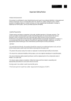
Important Safety Notice 3 1. Exploded Diagram 4 2. Wiring connectivity diagram 5 3. Mechanical Instruction 6 4. Disassembly and Assembly SOP 7 5. Troubleshooting 15 6. FRU List ...17 Safety Notice Any person attempting to service this chassis must familiarize with the chassis and be aware of - Acer B247YC | Lifecycle Extension Guide - Page 3
the safe, reliable operation of all series products. The service providers recommended by vender should being aware of notices listed in this service manual in order to minimize the risk of personal injury when perform service procedures. Furthermore, the possible existed improper repairing method - Acer B247YC | Lifecycle Extension Guide - Page 4
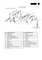
1.1 Product Exploded Diagram 1. Exploded Diagram ACER B247Y 4 Item ODM DESCRIPTION 1 ASSY BZL 2 PCBA LED BD 3 SCRW FPH M2.5*6 B-ZN 4 LCDM 23.8W M238HCA-L3B P 5 MID-FRAME 6 SPK 7 PCBA IF BD 8 SCRW 9 PCBA USB BD 10 PCBA SPS BD 11 WIRE 6/6P 1061#30 LED B246WL 12 MYLAR Item ODM DESCRIPTION 13 SCRW - Acer B247YC | Lifecycle Extension Guide - Page 5
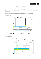
ACER B247Y 5 2. Wiring connectivity diagram There are two types of wiring diagrams for model B247Y. The wiring connectivity position will be different according to the ACTUAL PCBA connector position. Please base on different SKU refer to below diagram. NOTE: INF BD= Interface Board, PWR BD=Power - Acer B247YC | Lifecycle Extension Guide - Page 6
ACER B247Y 6 3. Mechanical Instruction Tools Required List the type and size of the tools that would typically can be used to disassemble the product to a point where components and - Acer B247YC | Lifecycle Extension Guide - Page 7
ACER B247Y 7 4. Disassembly and Assembly SOP B247Y 4.1 Disassembly Procedures Preparation before disassemble 1.Clean the room for disassemble 2.Identify the area for monitor 3.Check the position that the monitors be placed and the quantity of the monitor ;prepare the area for material flow; - Acer B247YC | Lifecycle Extension Guide - Page 8
ACER B247Y 8 S3 Disassemble the speaker from the MF Tear off tapes on the speaker wire. Extract the connect of the speaker from the PCBA. Disassemble the speaker from the MF(Middle Frame). S4 Disassemble the USB SIDE BD (This step is only for SKU with USB) PICTURE 1 Tear off the Mylar on the - Acer B247YC | Lifecycle Extension Guide - Page 9
ACER B247Y 9 S6 Disassemble the Trim PICTURE 1 Unlock two screws from the ASSY TRIM as picture 1. Disassemble the ASSY TRIM from the MF. Disassemble the PCBA LED BD from the ASSY TRIM as picture 2. Disassemble FFC LED from the PCBA LED BD as picture 3 PICTURE 2 PICTURE 3 LED BD LED BD S7 - Acer B247YC | Lifecycle Extension Guide - Page 10
ACER B247Y 10 S8-2 Disassemble the I/F BD and P/BD from SHD. Unlock 5 screws from the PCBA as the picture 1. Disassemble the I/F BD from the SHD and extract the P/BD wire. Extract the FFC LVDS from the I/F BD. Disassemble the P/BD from the SHD and extract the P/BD wire from the Power BD. 5 4 IF/ - Acer B247YC | Lifecycle Extension Guide - Page 11
ACER B247Y 11 4.2 Assembly Procedures Preparation before assemble: 1.Clean the room for work 2.Identify the area for material 3.Prepare the implement, equipment, materials as bellow: 1) working table 2) Screw-driver 3) Knife 4) glove 5) cleaning cloth 6) ESD protection After unplugging the power - Acer B247YC | Lifecycle Extension Guide - Page 12
ACER B247Y 12 S1-2 Assemble the MAIN board and power board. Picture 1 Put the SHD on the worktable. Insert P/BD wire to the Power BD and Locate the Power BD into the SHD as the picture 1. Insert FFC LVDS to the I/F BD as picture 2. Insert the wire on the P/BD to the I/F BD. Locate the I/F BD into - Acer B247YC | Lifecycle Extension Guide - Page 13
ACER B247Y 13 S4 Assemble the lamp wire PICTURE 1 Insert the big connector of the lamp wire to the P/BD .Stick 1 piece BOPP tape to fasten the lamp wire as the picture 1. Affix a Mylar on the left hole of the SHD as the picture 2. Tear off the four gums on the FFC LED. Stick the FFC LED on - Acer B247YC | Lifecycle Extension Guide - Page 14
ACER B247Y 14 S7 Assemble the speaker on the MF Insert the speaker connect to the I/F BD as the picture. Arrange the wire of the speaker (Attention: Keep the speaker wire straight, and the middle of the speaker wire is not allowed to be placed on the step of the panel.) Tear four BOPP tapes and - Acer B247YC | Lifecycle Extension Guide - Page 15
ACER B247Y 15 TROUBLESHOOTING 5. Troubleshooting Before sending your LCD monitor for servicing, please check the trouble-shooting list below to see if you can self-diagnose the problem. (VGA Mode) Problems Current Status Remedy LED ON Using OSD, adjust brightness and contrast to maximum - Acer B247YC | Lifecycle Extension Guide - Page 16
ACER B247Y 16 (HDMI/DP Mode) Problems Current Status LED ON Remedy Using OSD, adjust brightness and contrast to maximum or reset to their default settings. No Picture LED OFF LED displays - Acer B247YC | Lifecycle Extension Guide - Page 17
-date information available on your regional web or channel. For whatever reasons a part number change is made, it will not be noted on the printed Service Guide. For AUTHORIZED SERVICE PROVIDERS, your office may have a DIFFERENT part number code from those given in the FRU list of this printed
-
 1
1 -
 2
2 -
 3
3 -
 4
4 -
 5
5 -
 6
6 -
 7
7 -
8
-
9
-
10
-
11
-
12
-
13
-
14
-
15
-
16
-
17
 |
 |

Acer Monitor B247Y
LIFECYCLE EXTENSION
GUIDE