Acer B247YC Lifecycle Extension Guide - Page 5
NOTE: INF BD= Interface Board, PWR BD=Power Board, CTRL BD= Control Board
 |
View all Acer B247YC manuals
Add to My Manuals
Save this manual to your list of manuals |
Page 5 highlights
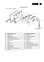
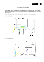
ACER B247Y 5 2. Wiring connectivity diagram There are two types of wiring diagrams for model B247Y. The wiring connectivity position will be different according to the ACTUAL PCBA connector position. Please base on different SKU refer to below diagram. NOTE: INF BD= Interface Board, PWR BD=Power Board, CTRL BD= Control Board 1. SKU with USB. 2. SKU without USB.
-
 1
1 -
 2
2 -
 3
3 -
 4
4 -
 5
5 -
 6
6 -
 7
7 -
 8
8 -
 9
9 -
 10
10 -
 11
11 -
12
-
13
-
14
-
15
-
16
-
17
 |
 |

ACER B247Y
5
2. Wiring connectivity diagram
There are two types of wiring diagrams for model B247Y. The wiring connectivity position will be
different according to the ACTUAL PCBA connector position. Please base on different SKU refer to
below diagram.
NOTE: INF BD= Interface Board, PWR BD=Power Board, CTRL BD= Control Board
1. SKU with USB.
2. SKU without USB.