Airlink AICAP650 User Manual
Airlink AICAP650 Manual
 |
View all Airlink AICAP650 manuals
Add to My Manuals
Save this manual to your list of manuals |
Airlink AICAP650 manual content summary:
- Airlink AICAP650 | User Manual - Page 1
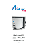
SkyIPCam 650 Model # AICAP650 User's Manual Ver. 1.0 - Airlink AICAP650 | User Manual - Page 2
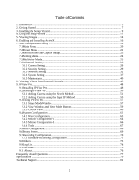
Menu ...22 7.3 Record Video and Capture Image 23 7.4 Setting Menu...24 7.5 Multiview Mode...25 7.6 Advanced Setting ...26 7.6.1 Camera Setting...26 7.6.2 Security Setting...29 7.6.3 Network Account ...75 9.11 About...76 Frequently Asked Questions ...77 Specification ...79 Technical Support ...81 2 - Airlink AICAP650 | User Manual - Page 3
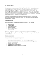
bundled Setup Wizard and IPView Pro software, managing and viewing multiple IP Cameras is simple and efficient. Instructions for installing and configuring this product can be found in this manual. Before you install and use this product, please read this manual carefully for proper operation of the - Airlink AICAP650 | User Manual - Page 4
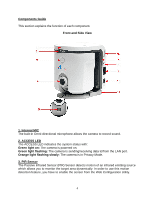
Components Guide This section explains the function of each component. Front and Side View 1. Internal MIC The built-in Omni-directional microphone allows the camera to record sound. 2. ACCESS LED The ACCESS LED indicates the system status with: Green light on: The camera is powered on. Green light - Airlink AICAP650 | User Manual - Page 5
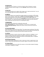
port. Please refer to Section 7.6.2 Security Setting for information about storing image files to the USB device via motion sensor triggers and/or via Category 5 twisted-pair cable). The port supports the NWay protocol, allowing the camera to automatically detect or negotiate the transmission speed - Airlink AICAP650 | User Manual - Page 6
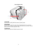
Rear and Bottom View 1. Screw Hole The screw hole is used to attach the camera to a stand or tripod. 2. Reset Button Press the button to reboot the camera. Press and hold the button for 5 seconds will reset the camera' settings to the factory default. Alternatively, you can perform reboot or factory - Airlink AICAP650 | User Manual - Page 7
to your network. 2. Install the Setup Wizard. 3. Configure the IP Camera using the Setup Wizard. Please follow the steps in this Manual carefully to ensure proper setup of the IP Camera. Caution: The IP Camera is designed for indoor use only. Direct exposure to sunlight may cause permanent damage - Airlink AICAP650 | User Manual - Page 8
other end to one of the LAN ports of the router or switch. Step 3 Power on the IP Camera by connecting one end of the supplied power adapter to the power jack of the Camera and connecting the other end to an electrical outlet. Step 4 Verify that the LED lights on the - Airlink AICAP650 | User Manual - Page 9
3. Installing the Setup Wizard Step 1 Insert the provided CD and wait for the autorun screen to appear. Step 2 Click on Install Setup Wizard. Note: If the autorun screen does not appear automatically, go to Start, Run, type D:\ Setup\Setup.exe (where D is the letter of your CD drive) and click OK. - Airlink AICAP650 | User Manual - Page 10
Step 4 Click Yes to accept the License Agreement. Step 5 Click Next to accept the default Destination Folder. Step 6 Click Finish to complete the installation. 10 - Airlink AICAP650 | User Manual - Page 11
4. Using the Setup Wizard Step 1 Go to Start > (All) Programs > AirLink101 IP Camera Setup Wizard > AirLink101 IP Camera Setup Wizard. Step 2 Select the IP Camera you want to configure from the list and click on the Wizard button. 11 - Airlink AICAP650 | User Manual - Page 12
Step 3 If the Camera's default IP address is on a different subnet, the following message the Admin ID and Password and click OK. Step 5 The Wizard will automatically generate an IP address for the camera, if this address is not in use by any other device in your local network, click OK. Otherwise, - Airlink AICAP650 | User Manual - Page 13
Next. Optionally, you can change the password by checking on the Change box and entering the new password. Step 7 If you need to change the Camera's IP address because another network device is already using the same address, you can assign a new address here and click Next. Step 8 Verify that all - Airlink AICAP650 | User Manual - Page 14
from within the same local area network as the IP Camera. To view images from an external network such as the Internet, please refer to Section 8 of this manual for further instructions. Step 1 At the Setup Wizard, select the desired camera from the list and click on the Web Config button. Step - Airlink AICAP650 | User Manual - Page 15
. If you did not change the default password, you will be prompted to do so before accessing the camera. Step 4 The Main menu along with the live video appears on screen. The IP camera is ready for use now. Note: ActiveX must be installed and enabled on your Web Browser (Internet Explorer - Airlink AICAP650 | User Manual - Page 16
6. Enabling and Installing ActiveX If no image appears on the web browser (Internet Explorer), follow the steps below to enable and install ActiveX Step 1 Open Internet Explorer and go to Tools > Internet Options. Step 2 Select the Security tab and click on Custom Level. 16 - Airlink AICAP650 | User Manual - Page 17
Step 3 Verify the following settings are selected. Click OK when done: • Automatic prompting for ActiveX controls: Enable • Download signed ActiveX controls: Prompt • Run ActiveX controls and plug-ins: Enable Step 4 Close Internet Explorer and re-launch the Web Config screen. 17 - Airlink AICAP650 | User Manual - Page 18
Step 5 Click on the ActiveX Control prompt. Step 6 Select Install ActiveX Control. Step 7 Click on Install to install the ActiveX Control. Step 8 After the ActiveX Control is installed you should see the live video on Internet Explorer. 18 - Airlink AICAP650 | User Manual - Page 19
). If you are not using Internet Explorer, you can use the bundled IPView Pro software to manage the camera. See Section 8 for detail. Step 1 Open your Web Browser (Internet Explorer), enter the default IP Address of the Camera 192.168.1.240 in the Address Bar and press Enter. Note: If you have - Airlink AICAP650 | User Manual - Page 20
The index page displays the menu bar, information bar, and the live video. 7.1 Main Menu Digital Zoom In/Out In the Main menu, click the Digital Zoom Bar to zoom in and out of the displayed image by 1X, 2X, or 4X. 20 - Airlink AICAP650 | User Manual - Page 21
in the area of the live video to change the position of the lens. Flash LED On/Off The camera is equipped with a powerful Flash LED that allows you to capture clear images in a dark environment. In low light environment, click the Flash LED button ( ) to turn on the flash light of - Airlink AICAP650 | User Manual - Page 22
7.2 Preset Menu You can preset up to 8 positions for the camera from the Preset menu. This enables you to move the camera lens to the desired position quickly. To set up the position, move the camera lens to the desired position first and select the number (1~8) from the pull-down list, then click - Airlink AICAP650 | User Manual - Page 23
Browse button to browse to the destination folder. AVI file name: Assign the file name for the recorded video clip. JPEG file name: Assign the file name for the captured still image. Recording restriction: Set up the limit for the recorded/captured file by Nothing, File size, or Time. Click OK when - Airlink AICAP650 | User Manual - Page 24
degree(s): Allows you to change the moving range (1°~10°) when you pan the camera lens position. Vertical degree(s): Allows you to change the moving range (1°~10°) when you tilt the camera lens position. Quality: You can set the image quality by selecting Low, Med, or High. Voice: Select On/Off to - Airlink AICAP650 | User Manual - Page 25
to Multiview Mode. Click the Multiview Mode button in the Setting menu to change to the following multiview screen. To add an additional camera, enter the new camera's IP address and click Register. You can select the refresh interval from the Refresh interval drop-down list. To return to the Home - Airlink AICAP650 | User Manual - Page 26
System setting, and Maintenance. 7.6.1 Camera Setting The Camera setting provides three sub-menus: Camera setting, Date/Time setting, and Buzzer setting. Camera Setting Camera name: Assign a descriptive name for the camera. Image size: Select the desired image resolution from three formats: 176x144 - Airlink AICAP650 | User Manual - Page 27
the camera's location. The options include: 50Hz, 60Hz, or Outdoor. Flip Image: Select Horizontal to display the image in a horizontal mirror mode. Select Vertical to display the image in synchronized with the NTP server you selected. Manual setting: Select this option to set up the date and time - Airlink AICAP650 | User Manual - Page 28
Buzzer Setting If you enabled the camera's buzzer feature, you can setup the buzzer type for the following action: System start, Motion detected, Scheduled operation, and Buzzer button pressed. The available buzzer - Airlink AICAP650 | User Manual - Page 29
the operational time frame for the sensor. If you want to have the camera constantly detect motion, leave these two options blank. Action: Select the camera's response when motion is detected: Buzzer, Email, FTP, Flash the light, and Save image to USB disk. Click Setup to save the settings. 29 - Airlink AICAP650 | User Manual - Page 30
the Interval box. For example, if you set up 10 minutes, the camera will act every 10 minutes during the assigned time period. Action: Select the camera's action when it reaches the scheduled time: Buzzer, Email, FTP, Flash the light, and Save image to USB disk. Click Setup to save the settings. 30 - Airlink AICAP650 | User Manual - Page 31
allows you to assign the time period for the users to view the live video. When this feature is enabled, the users can only access the camera to view the live video during the specified time period. During other times, the message "Access restricted. Image can not be viewed" will be displayed on the - Airlink AICAP650 | User Manual - Page 32
to assign a static IP address to the camera. Static IP: You can manually assign a static IP address to the camera. PPPoE: If your application requires a direct connection from a DSL modem through the camera's RJ-45 LAN port, select this option and enter the User ID and Password into the respective - Airlink AICAP650 | User Manual - Page 33
Dynamic DNS Setting This camera supports Dynamic DNS feature which allows you to assign a fixed host and domain name to a dynamic Internet IP address. Please note that you have to sign up for DDNS service with one of the listed service providers before using this feature. Select the Enable Dynamic - Airlink AICAP650 | User Manual - Page 34
UPnP Setting UPnP allows peer-to-peer connectivity between various network devices seamlessly. Select Enable/Disable in the UPnP setting option to enable/disable this function. Click Setup to save the settings. 34 - Airlink AICAP650 | User Manual - Page 35
server field according to your network configuration. POP server will be used when the Authentication mode is set to POP before SMTP. User name: Enter the user name to log into the mail server. Authentication mode: Select the correct authentication mode according to the setting of the mail server - Airlink AICAP650 | User Manual - Page 36
name: Enter the user name to log into the FTP server. Password: Enter the password to log into the FTP server. Directory: Enter the directory for uploading the images. Fixed filename: Select this box to enable fixed filename and enter the filename. Passive mode: Select this box to enable passive - Airlink AICAP650 | User Manual - Page 37
7.6.4 System Setting The System setting page provides two sub-menus that allow you to manage users of the camera: Administrator password and User setting. Administrator Password This sub-menu allows you to change the administrator's login password. Enter the new password twice in the New password - Airlink AICAP650 | User Manual - Page 38
this feature is enabled, you have to enter the username and password in the login window to access the camera. When the option is disabled, you can directly access the camera as a Power user without entering the username and password; however, once you try to access the setup page, you will be asked - Airlink AICAP650 | User Manual - Page 39
: Allowed to use some basic functions of the camera such as Zoom In/Out, Buzzer, Flash LED, camera's lens position, Preset menu, and switching to multiview mode. Power User View Guest: Allowed to view live video, and record/capture the video/image by using the Record/Snapshot buttons. Guest View - Airlink AICAP650 | User Manual - Page 40
page provides six sub-menus: USB Removal, Reboot, Factory Reset, Firmware Update, Information, and Log Display. USB Removal To remove the hold the Privacy Mode button for 5 seconds until the camera activates the buzzer indicating that you can remove the USB storage device from the USB port safely - Airlink AICAP650 | User Manual - Page 41
Reboot Click Reboot to restart the camera while retaining all the settings. Factory Reset Click Yes to return all the settings to factory default. 41 - Airlink AICAP650 | User Manual - Page 42
Backup Setting You can save the camera's settings to the local hard drive by using the Backup Setting feature. Click Backup to save the settings. Follow the on-screen instructions to save the settings. The default filename is Config.cfg Restore Setting You can restore previously saved settings by - Airlink AICAP650 | User Manual - Page 43
-menu allows you to update the Camera to the latest firmware. You can check our website at www.airlink101.com to see if there is a newer firmware available for download. Step 1 Download the new firmware from our web site at www.airlink101.com Step 2 Unzip the new firmware. Step 3 Click on the Browse - Airlink AICAP650 | User Manual - Page 44
Information This sub-menu provides general information of the camera including the firmware version, networking configuration, and security settings. Log Display This sub-menu provides a list that contains the events and actions of the camera. 44 - Airlink AICAP650 | User Manual - Page 45
has an Internet IP Address (WAN IP) of 172.16.1.1 assigned by the Internet Service Provider (ISP). The ISP's DNS IP Address is 10.0.0.1 and 10.0.0.2 Network B = Location of the remote client trying to access the Camera. Step 1 From one of the computers in Network A, open the web browser (Internet - Airlink AICAP650 | User Manual - Page 46
Step 3 Go to Setting Menu > Advanced Setting > Network Setting > IP/Port Setting. Step 5 Enter your ISP's DNS IP Address at the Primary DNS and Secondary DNS fields. 46 - Airlink AICAP650 | User Manual - Page 47
in use by any other application on your network. Step 7 Click Setup to apply the new settings. Now the Camera with IP Address of 192.168.1.240 has port 80 Open. Step 8 From one of the computers in Network .1.1:80 The remote client in Network B should be able to see the images from the Camera now. 47 - Airlink AICAP650 | User Manual - Page 48
9. IPView Pro The bundled IPView Pro software features a user-friendly interface that allows you to manage, view, and configure multiple IP Cameras on your network. If your web browser doesn't support ActiveX, you may use this software to view the live video instead. Follow the steps below if you - Airlink AICAP650 | User Manual - Page 49
Step 4 Click Yes to accept the License Agreement. Step 5 Click Next to accept the default Destination Folder. Step 6 Click Finish to complete the installation. 49 - Airlink AICAP650 | User Manual - Page 50
9.2 Starting IPView Pro To start IPView Pro, go to Start > (All) Programs > Airink101 IPView Pro > Airlink101 IPView Pro The main screen will appear as below: Note: Be sure to set your screen resolution to 1024 x 768 or higher. 50 - Airlink AICAP650 | User Manual - Page 51
Method Before you can do anything, the camera must be added to the Camera List first. If you have more than one camera, you'll need to add the additional cameras to the list as well. The Search Method is the easiest way to add your local cameras to the list. Step 1 Click on the - Airlink AICAP650 | User Manual - Page 52
Step 3 Verify your camera is connected to your network and is powered on. Click on the Search button. Step 4 Select your camera from the Add Camera list and click on Add Camera. 52 - Airlink AICAP650 | User Manual - Page 53
Step 5 Enter the User Name and Password for the camera. (Default is admin for both). Step 6 You should see your camera added to the Camera List. Step 7 Click Save to apply the changes. 53 - Airlink AICAP650 | User Manual - Page 54
Step 8 Click on the System Configuration button to close the System Configuration Window. You should now see live images from the camera. Note: If you want to add a camera located on a remote network (through the Internet), you must add the camera using the Input IP method described below. 54 - Airlink AICAP650 | User Manual - Page 55
An alternative way to add your local camera to the Camera List is to use the Input Method. If you want to add a camera located on a remote network (through the Internet), you must use this method. Step 1 Select the Input IP tab. Step 2a For local camera, enter the local IP Address of your - Airlink AICAP650 | User Manual - Page 56
router and the port number of the open HTTP Port of the remote camera and click Add Camera. Step 3 Enter the User Name and Password for the camera. (Default is admin for both). Step 4 You should see your camera added to the Camera List. Step 5 Click Save to apply the changes. Step 6 Click on the - Airlink AICAP650 | User Manual - Page 57
the various features of IPView Pro. 9.3.1 Status Mode Window The Status Mode Window displays a list of cameras that are added to IPView Pro as well as the status of each selected camera. Select the desired camera from the list then click on the Change Status Mode button to view the status of the - Airlink AICAP650 | User Manual - Page 58
various functions. From left to right: Connect/Disconnect: Connects or disconnects the video signals from the selected camera. Rotate Image Angle: Rotates the angle of the video. Snapshot: Takes a snapshot image of the current video. When you click on this button, a window will appear asking you to - Airlink AICAP650 | User Manual - Page 59
select the desired viewing mode. From left to right: Up/Down Arrows: If you have more than one camera in your network, you can use the Up/Down Arrow Buttons to view the videos from each camera. View Modes: Select the desired view mode. The view window can display up to 16 - Airlink AICAP650 | User Manual - Page 60
to Exit or Minimize IPView Pro. Record: Click on the Record button and select Manual Record to record the video immediately to your hard drive. If you select Schedule Record or Motion Record, the camera will record the videos according to the corresponding settings in System Configuration. To stop - Airlink AICAP650 | User Manual - Page 61
: Click on the System Configuration Button to open the System Configuration Window. Arrow Buttons: Click on the arrow buttons to change the position of the camera lens. The home button returns the lens to the home position. 61 - Airlink AICAP650 | User Manual - Page 62
of IPView Pro and all the cameras that are added to the Camera List. The Camera Configuration page allows you to add the cameras in your network to IPView Pro's Camera List. For instructions on how to do add your cameras, please refer to Section 9.2.1 Adding Camera Using the Search Method. 62 - Airlink AICAP650 | User Manual - Page 63
9.4.1 Web Configuration The Web Configuration page allows you to access the Web Configuration Utility of the selected camera. If you have more than one camera, you can use the drop-down menu to select the desired camera. 63 - Airlink AICAP650 | User Manual - Page 64
-1 The Motion Configuration-1 page allows you to set the Motion Detection settings. Select the desired camera from the drop-down menu. Detect Region: When you select Full picture, the camera will monitor the entire screen. Sensitivity Level: Adjust the slide bar to set the sensitivity level - Airlink AICAP650 | User Manual - Page 65
. Click Add Region and then use the mouse to draw an area in the viewing screen. When motion is detected within the specified area, the camera starts to record automatically. You can set multiple areas in the viewing screen. Click Delete Region to remove the area selected. Click Clear All Region - Airlink AICAP650 | User Manual - Page 66
9.4.3 Motion Configuration-2 The Motion Configuration-2 page allows you to set the desired action when motion is detected. Select the desired camera from the drop-down menu. Motion Options: Check on each box to enable the desired action when motion is detected. Invoke Alarm: A notice will appear - Airlink AICAP650 | User Manual - Page 67
drop-down menu. Reset: Click on the Reset button to reset the selected camera. Factory Reset: Click on the Factory Reset button to reset the camera and return all of the camera's settings to factory default. Update Firmware: Click on Browse to locate the new firmware and click Update to update the - Airlink AICAP650 | User Manual - Page 68
e-mail. Mail From: Enter the sender's e-mail address. Mail To: Enter the recipient's e-mail address. Subject: Enter the title of the e-mail. User Name: Enter the user name for logging into the Mail Server. Password: Enter the password for logging into the Mail Server. Interval Time: Enter the time - Airlink AICAP650 | User Manual - Page 69
9.6 Proxy Server The Proxy Server page allows you to specify the use of a proxy server. Proxy Server: Check on this box to enable the use of a proxy server. Address: Enter the IP Address of the desired proxy server. Port: Enter the port number for the proxy server. Bypass proxy server for local - Airlink AICAP650 | User Manual - Page 70
indicates where the recorded videos will be saved. Recycle: Check this box to clear the recorded files when the specified Reserved HDD space for each camera is filled. (200 MB - 50000 MB). Resume last time's state of recording: Check this box to resume the same state of recording as the previous - Airlink AICAP650 | User Manual - Page 71
9.7.1 Schedule-Recording Configuration The Schedule-Recording Configuration page allows you to setup automated recording at the scheduled time. Date Mode Select the desired camera from the drop-down menu. Specify the Start Date/Time and the Stop Date/Time and click Add. Click Save to apply the - Airlink AICAP650 | User Manual - Page 72
Week Mode Select the desired camera from the drop-down menu. Specify the Start and Stop time for each week and click on the Days of the week that you want - Airlink AICAP650 | User Manual - Page 73
9.8 Others The Others page allows you to set the time interval to scan through each camera in your network. Use the drop-down menu to select the time interval (in seconds) for each scan. Click Save to apply the changes. Click on the Scan Mode button to begin scanning. 73 - Airlink AICAP650 | User Manual - Page 74
9.9 Log List The Log List page displays the log of the selected camera. Select the desired camera from the drop-down menu to display its log. 74 - Airlink AICAP650 | User Manual - Page 75
9.10 Account The Account page allows you to setup a user name and password to log in to IPView Pro. Enter the desired Admin ID and Password. Login password check: Check this box to enable the login prompt when you start IPView Pro and when you unlock the Key Lock button. 75 - Airlink AICAP650 | User Manual - Page 76
9.11 About The About page provides the version number of IPView Pro. 76 - Airlink AICAP650 | User Manual - Page 77
is used to compress the digital image? The camera utilizes the JPEG image compression technology, providing high quality images for users. JPEG is adopted since it is a standard for image compression and can be applied to various web browser and application software without the need to install extra - Airlink AICAP650 | User Manual - Page 78
the CMOS sensor. Q: There is bad focus on the camera, what should be done? A: You can adjust the camera's focus manually by turning the lens clockwise or counter-clockwise. Q: How can I fix noisy images? A: The video images might be noisy if the camera is in a very dim environment. To solve this - Airlink AICAP650 | User Manual - Page 79
camera image display is incorrect. Through the Web Configuration Utility, you can adjust the display parameters such as brightness, contrast, hue, and light frequency. Q: There are no images does not support ActiveX, you can use the bundled IPView Pro software instead. Specification Image Sensor - Airlink AICAP650 | User Manual - Page 80
Communication LAN Port: RJ-45, 10/100M auto-sensed, Auto MDI-X Communication Protocol: HTTP, FTP, TCP/IP, UDP, ARP, ICMP, DHCP, POP3, SMTP, PPPoE, DDNS, UPnP Power Power Supply: DC 5V 2.5A, switching type Power Consumption: 7.5W @ 1500mA/5V (max.) Environment Operating Temperature: 0°C ~ 40°C - Airlink AICAP650 | User Manual - Page 81
Technical Support E-mail: [email protected] Toll Free: 1-888-746-3238 Web Site: www.airlink101.com * Actual data throughput will vary. Network conditions and environmental factors lower actual data throughput rate. Specifications are subject to change without notice. All products
-
 1
1 -
 2
2 -
 3
3 -
 4
4 -
 5
5 -
 6
6 -
 7
7 -
8
-
9
-
10
-
11
-
12
-
13
-
14
-
15
-
16
-
17
-
18
-
19
-
20
-
21
-
22
-
23
-
24
-
25
-
26
-
27
-
28
-
29
-
30
-
31
-
32
-
33
-
34
-
35
-
36
-
37
-
38
-
39
-
40
-
41
-
42
-
43
-
44
-
45
-
46
-
47
-
48
-
49
-
50
-
51
-
52
-
53
-
54
-
55
-
56
-
57
-
58
-
59
-
60
-
61
-
62
-
63
-
64
-
65
-
66
-
67
-
68
-
69
-
70
-
71
-
72
-
73
-
74
-
75
-
76
-
77
-
78
-
79
-
80
-
81
 |
 |

SkyIPCam 650
Model # AICAP650
User’s Manual
Ver. 1.0