Airlink AICAP650 User Manual - Page 8
Step 2, Step 3, Step 4
 |
View all Airlink AICAP650 manuals
Add to My Manuals
Save this manual to your list of manuals |
Page 8 highlights
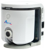
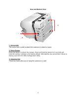
Step 2 Connect one end of the network cable to the IP Camera and connect the other end to one of the LAN ports of the router or switch. Step 3 Power on the IP Camera by connecting one end of the supplied power adapter to the power jack of the Camera and connecting the other end to an electrical outlet. Step 4 Verify that the LED lights on the Camera are lit. If not, verify that all the connections are secure and try again. 8
-
 1
1 -
2
-
 3
3 -
 4
4 -
 5
5 -
 6
6 -
 7
7 -
 8
8 -
 9
9 -
 10
10 -
 11
11 -
 12
12 -
 13
13 -
14
-
15
-
16
-
17
-
18
-
19
-
20
-
21
-
22
-
23
-
24
-
25
-
26
-
27
-
28
-
29
-
30
-
31
-
32
-
33
-
34
-
35
-
36
-
37
-
38
-
39
-
40
-
41
-
42
-
43
-
44
-
45
-
46
-
47
-
48
-
49
-
50
-
51
-
52
-
53
-
54
-
55
-
56
-
57
-
58
-
59
-
60
-
61
-
62
-
63
-
64
-
65
-
66
-
67
-
68
-
69
-
70
-
71
-
72
-
73
-
74
-
75
-
76
-
77
-
78
-
79
-
80
-
81
 |
 |

8
Step 2
Connect one end of the network cable to the IP Camera and connect the other
end to one of the
LAN
ports of the router or switch.
Step 3
Power on the IP Camera by connecting one end of the supplied power adapter
to the power jack of the Camera and connecting the other end to an electrical outlet.
Step 4
Verify that the LED lights on the Camera are lit. If not, verify that all the
connections are secure and try again.